
Author: Nima Rad – Radonix Automation
Short answer: A servo motor in CNC machine is an electric motor with a feedback device (encoder or resolver) driven by a servo drive in a closed loop. The loop continuously corrects torque, speed and position, which gives CNC axes high accuracy, fast response and stable torque across a wide speed range, even under changing loads.
In industrial automation, and especially in CNC systems, the servo motor is the actuator that turns controller commands into precise motion. This guide covers how a CNC servo axis is built, the main motor and feedback types, the specifications you must understand, how to size an axis, how to wire it for noise immunity, and a checklist for selecting the right system.
What Is a Servo Motor in CNC Machine?
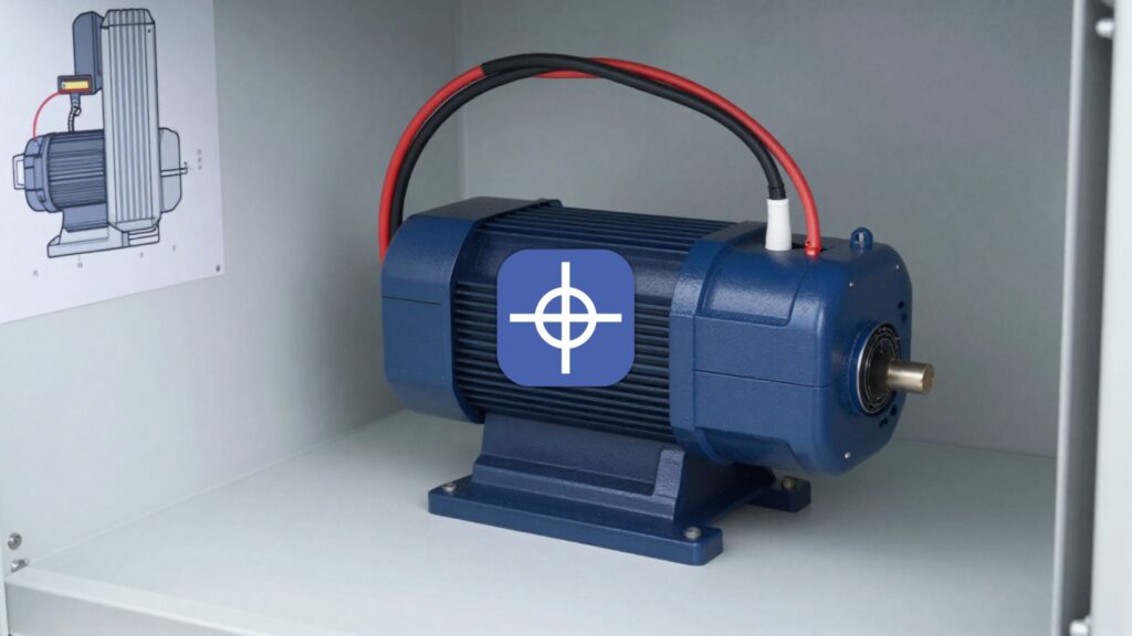
A servo motor is an electric motor integrated with a feedback device (position and/or speed sensor) and controlled by a servo drive operating in a closed-loop architecture. The system continuously measures actual performance and corrects torque, speed and position in real time. The result is:
- high positional accuracy,
- fast dynamic response,
- stable torque across a wide speed range.
A typical CNC servo axis consists of four parts:
1. Servo Motor
Most commonly a permanent magnet synchronous motor (PMSM) or an industrial brushless DC (BLDC) motor.
2. Feedback Device
- Incremental encoder
- Absolute encoder
- Resolver (for harsh environments)
- Linear scale (for direct table-position feedback in high-precision CNC systems)
3. Servo Drive (Amplifier)
Includes the inverter stage, the current, speed and position controllers, protection circuits and industrial communication interfaces.
4. CNC or PLC Controller
Generates trajectory commands: target position, target speed, acceleration and jerk profile, and multi-axis coordination.
Why Servo Motors Dominate Professional CNC
- True closed-loop position control. Compensates automatically for load changes, friction, voltage variation and temperature.
- High-bandwidth response. Critical for sharp corners, sudden trajectory changes and vibration control.
- High low-speed torque with overload capability. Servo motors can typically deliver a multiple of their rated torque for short durations.
- Accuracy under variable load. Positioning precision is maintained even when driving heavy tables, gearbox systems or servo spindles.
Types of Servo Motors Used in CNC
By Motor Technology
- AC servo (PMSM / brushless): the most common in CNC and robotics, with high efficiency and low maintenance.
- Brushed DC servo: older technology that needs brush maintenance, still found in legacy systems.
- Linear servo motor: provides direct linear motion with high speed and precision, at higher system cost.
By Feedback Type
- Incremental encoder: typically requires homing after power-up. See incremental encoders in CNC.
- Absolute encoder: retains position data and enables faster, safer restarts. See absolute encoders in CNC.
- Resolver: more resistant to heat and electrical noise.
Inside the Servo Drive: Cascaded Control Loops
Industrial servo drives typically use a cascaded control architecture:
- Current (torque) loop: the fastest, controlling motor phase currents to produce precise torque.
- Velocity loop: maintains the commanded rpm and compensates for load disturbances.
- Position loop: the outermost, ensuring the axis reaches its target with minimal error and overshoot.
Inner loops run at higher sampling frequencies and determine overall system responsiveness.
Key Servo Motor Specifications
Torque Ratings
- Rated torque: continuous torque without overheating.
- Peak torque: short-duration overload capability.
- Holding torque at zero speed: maintained by current-loop control.
Speed Ratings
- Rated speed
- Maximum speed
Mechanical limits (bearings, rotor balance) and electrical limits (bus voltage, back EMF) must both be evaluated. For worked calculations, see our guide to servo motor torque and RPM.
Inertia
- Motor inertia (Jm)
- Load inertia (Jl)
The inertia ratio (Jl/Jm) strongly affects stability and the effort needed to set up the axis. As a practical guideline, keeping the ratio below roughly 5 to 10 simplifies control and improves robustness.
Encoder Resolution
Typical encoder resolutions range from 17-bit to 23-bit. Linear positioning accuracy at the load also depends on screw pitch, pulley ratio or gearbox reduction.
Practical Servo Sizing for a CNC Axis
Sizing starts from mechanical analysis, not from the catalogue.
Required Torque
- Acceleration torque: T_acc = J_total × α (total inertia times angular acceleration).
- Load torque: T_load ≈ F × r, or derived from the ball-screw force-to-torque conversion.
Vertical axes (Z) require gravity compensation and often a holding brake or a mechanical counterbalance.
RMS Torque Check
Select the motor on RMS torque over the real duty cycle, not only on peak values. If RMS torque exceeds the rated torque, the motor will overheat even if the peak events are brief.
Voltage and Speed Matching
Verify that:
- the required speed lies within the motor torque curve,
- the drive bus voltage class (for example 220 VAC or 380 VAC) is correctly selected.
Feedback Selection
- Absolute encoder for fast recovery and high reliability.
- Resolver, or enhanced shielding, for noisy industrial environments.
Tuning a CNC Servo Axis: The Short Version
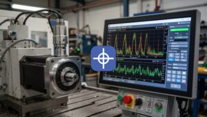
Improper setup makes axes oscillate at standstill, overshoot on direction changes, whine, or show high following error. The adjustable parameters include position gain, velocity-loop gains, velocity and acceleration feedforward, notch filters, inertia identification, torque limits and S-curve (jerk) control.
The most important principle: software cannot compensate for poor mechanics. Backlash, weak couplings, misaligned screws or low-quality bearings must be corrected mechanically first.
For the full procedure, follow the guide to servo motor tuning. To understand what the gain parameters do, read about servo gain. To change axis speed safely, see how to adjust servo motor speed, and to set up reference positions, see calibrating and resetting a servo motor.
Servo vs Stepper in CNC Systems
| Feature | Servo | Stepper |
| Feedback | Closed loop | Typically open loop |
| High-speed torque | Strong | Drops significantly |
| Accuracy under load | High | Risk of lost steps |
| Setup | Tuning required | Simpler |
| Cost | Higher | Lower |
| Professional CNC use | Excellent | Entry-level and light duty |
For a deeper comparison, read stepper vs servo motors.
Wiring and EMC Best Practices
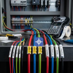
Many servo problems originate from electrical noise and grounding.
- Route motor and encoder cables separately.
- Ground cable shields correctly at the drive side.
- Use EMI filters or line chokes where required.
- Ground the motor body, cabinet and drive properly.
- Design safe, reliable brake circuits for vertical axes.
Recognised Servo Brands and Ecosystems
Major industrial ecosystems include Yaskawa, Mitsubishi Electric, FANUC, Siemens, Allen-Bradley, Beckhoff, Delta Electronics, Panasonic and HEIDENHAIN. Selection should consider ecosystem compatibility, service availability and integration with the CNC controller architecture.
Checklist for Selecting a CNC Servo Axis
- Motion mechanism type (ball screw, rack and pinion, belt, gearbox)
- Load mass and inertia
- Required speed and acceleration
- RMS and peak torque validation
- Mechanical rpm limits and backlash
- Required encoder type and resolution
- Drive voltage class and regeneration handling
- EMC and wiring quality
- Safety requirements (STO, brake for the Z axis)
FAQ
What is a servo motor in a CNC machine?
A servo motor in a CNC machine is a closed-loop motor system with feedback that precisely controls position, speed and torque using a servo drive and a controller.
Why are servo motors preferred over steppers in professional CNC?
Servo motors provide higher torque at speed, real-time position correction, better accuracy under load and improved dynamic response compared with open-loop stepper systems.
What inertia ratio is recommended for a CNC servo axis?
For stable behaviour and easier setup, the load-to-motor inertia ratio is typically kept below about 5 to 10, depending on mechanical stiffness and control bandwidth.
Why does a CNC servo axis oscillate?
Oscillation is usually caused by excessive gain, mechanical resonance, backlash or poor structural rigidity. Both parameter adjustment and mechanical correction are needed.
Which feedback device should I choose?
Choose an absolute encoder for fast recovery and high reliability, an incremental encoder for cost-sensitive axes that can home at start-up, and a resolver or extra shielding in hot or electrically noisy environments.
Choose the Right Servo System
Servo motors remain the backbone of high-performance CNC machines. Correct selection, proper mechanical design, accurate sizing and disciplined setup determine whether an axis performs with precision and stability or struggles with vibration and positioning errors.
For expert guidance on selecting, sizing or commissioning servo systems for your CNC machine, contact Radonix or use the chatbot in the bottom right corner to speak directly with our technical team. For machine integration, compare Radonix CNC controller hardware for independent multi-axis motion, pulse/direction signals and industrial I/O.
For machine integration, compare Radonix CNC controller hardware for independent multi-axis motion, pulse/direction signals and industrial I/O. Radonix CNC controller hardware.