
Written by: Radonix R&D Team
Short answer: An incremental encoder converts shaft rotation into a stream of pulses. Two channels, A and B, are offset by 90° so the controller can tell direction and count position changes, while a Z (index) pulse marks one reference point per revolution for homing. It reports movement relative to a start point, so the axis must be homed after power-up.
Incremental encoders are among the most widely used feedback devices in CNC machines, servo drives and industrial automation. They turn mechanical rotation into electrical pulses so the controller can monitor shaft position, direction and speed in real time. For a comparison of all encoder families, see encoders in CNC machines.
What Is an Incremental Encoder?
An incremental encoder produces a series of pulses as its shaft rotates. The pulses represent relative movement, not an absolute position. This suits applications that need high-resolution measurement of speed and direction with fast response and simple interfacing. They are commonly mounted on servo and spindle motors, on axis drives (X, Y and Z), on robotic joints and on automated production equipment.
How Incremental Encoders Work
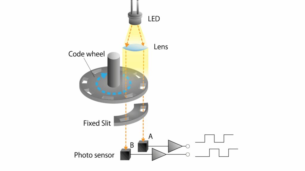
An optical incremental encoder has a rotating disc marked with transparent and opaque segments. An LED shines through the disc and a photodetector reads the alternating light pattern, converting each passing segment into a square-wave signal.
Most incremental encoders output three signals:
- A pulse: counts position changes.
- B pulse: the same pattern shifted by 90° from A, which reveals the direction of rotation.
- Z pulse (index): one reference pulse per revolution, used for homing.
From these the controller derives rotational speed, angular displacement and direction.
Signal Structure and Measurement
Because A and B are phase-shifted by 90°, the controller can distinguish forward from reverse rotation. The controller usually counts every edge of both channels (quadrature ×4 counting), so the number of counts per revolution is four times the encoder’s pulses per revolution (PPR). The Z pulse gives an electrical reference once per turn, which CNC machines use for zero-setting and homing moves.
Resolution: PPR and Accuracy
Resolution is stated in pulses per revolution (PPR). Typical ranges are:
| PPR | Typical use |
| About 1,000 | Basic automation |
| 2,500 to 5,000 | Higher-quality CNC and servo feedback |
| 10,000 and above | High-precision equipment |
Higher resolution allows smoother velocity estimation, finer positioning and better servo-loop behaviour, but it also raises signal frequency, so confirm the controller or drive input can handle the maximum pulse rate at your top axis speed. Final system accuracy also depends on the mechanics, not only on PPR.
Encoder Technology Types
| Technology | Principle | Strengths | Limitations |
| Optical | LED, photodetector and coded disc | Highest resolution and accuracy | Sensitive to dust, oil, vibration and contamination |
| Magnetic | Magnetic poles read by Hall sensors | Resistant to dust, oil and harsh environments | Lower resolution than optical |
| Inductive | Electromagnetic fields detect position | Durable in dirty or metallic environments, stable long term | Moderate resolution |
Electrical Output Types
| Output | Notes |
| TTL (5 V) | High-speed signal |
| HTL (10 to 30 V) | More noise-resistant, common in industrial automation |
| Open collector | Flexible but slower |
| Push-pull | Strong, noise-tolerant output |
| RS-422 differential | Preferred for CNC because of high noise immunity and stable long-distance transmission |
Match the output type and voltage to the controller or drive input to keep signal integrity under real operating conditions.
Common Error Sources and How to Reduce Them
- Jitter: random timing variation between pulse edges, caused by electrical noise or LED instability.
- Phase error: A and B must stay 90° apart; deviation can cause direction misinterpretation.
- Signal drop: momentary or complete loss of A, B or Z because of loose connectors, damaged cables or noise.
- Mechanical misalignment: if the encoder shaft is not aligned with the motor shaft, vibration and inconsistent pulses appear.
Mitigation: digital filtering, shielded industrial cables, differential RS-422 drivers and precision backlash-free couplings.
CNC Applications of Incremental Encoders
- Axis positioning feedback on X, Y and Z.
- Spindle speed control and orientation using the index pulse.
- Closed-loop correction for stepper and servo motors; see open loop vs closed loop control in CNC.
- Tool alignment and homing routines using the Z pulse.
With encoder feedback the controller can correct motion errors quickly, keep toolpaths consistent and hold tight tolerances. For motors that use these encoders, see servo motors in CNC.
Incremental vs Absolute Encoders
An incremental encoder is lower in cost and very simple, but loses its position when power is removed and needs a homing move on start-up. An absolute encoder reports a unique position at power-on. For axes where restart time or safety after power loss matters, read about absolute encoders in CNC.
Installation and Maintenance Guidelines
- Use backlash-free flexible couplings.
- Keep optical encoders clean and dust-free.
- Route shielded cable away from power lines.
- Confirm tight mounting to avoid shaft vibration.
- Inspect connectors regularly.
Following these practices prevents drift, pulse distortion and premature failure.
FAQ
How does an incremental encoder work?
A disc with transparent and opaque segments passes between a light source and photodetectors, producing A and B square waves 90° apart plus a once-per-turn Z pulse. The controller counts the pulses for position, speed and direction.
What do A, B and Z mean on an encoder?
A and B are the two quadrature channels used to count movement and detect direction. Z is the index pulse that marks one reference position per revolution.
Why does an incremental encoder need homing?
It only counts movement relative to a start point, so its position is lost at power-off. A homing move to a switch and the Z pulse re-establishes the reference.
What PPR do I need for a CNC axis?
It depends on the required resolution, the screw pitch or gear ratio and the maximum speed. Higher PPR improves resolution but increases signal frequency, so check the controller input limit.
Why use RS-422 differential outputs?
Differential signalling resists electrical noise and works over longer cables, which is why it is common in CNC systems.
Get Reliable Feedback on Every Axis
Incremental encoders give accurate, real-time feedback when matched to the controller, wired with shielding and installed with proper couplings. Contact Radonix or use the chatbot in the bottom right corner to discuss encoder inputs for your control system. For machine integration, compare Radonix CNC controller hardware for independent multi-axis motion, pulse/direction signals and industrial I/O.
For machine integration, compare Radonix CNC controller hardware for independent multi-axis motion, pulse/direction signals and industrial I/O. Radonix CNC controller hardware.