
Table of Contents
- Introduction
- Structure of the Pneumatic Cylinder
- Types of Pneumatic Cylinders
- Working Principle of the Pneumatic Cylinder
- Applications in CNC
- Advantages and Disadvantages
- Step-by-Step Installation
- Maintenance and Repair
- Conclusion
- References
Introduction
A pneumatic cylinder, also known as an air cylinder, is one of the key components in industrial automation systems, especially in computer numerical control (CNC) machines. This device converts the energy of compressed air into linear motion and plays a role in various operations such as clamping, tool changing, and part ejection. In this educational article, we cover the structure, types, working principle, applications, advantages, disadvantages, installation, and maintenance of the pneumatic cylinder in full detail.
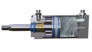
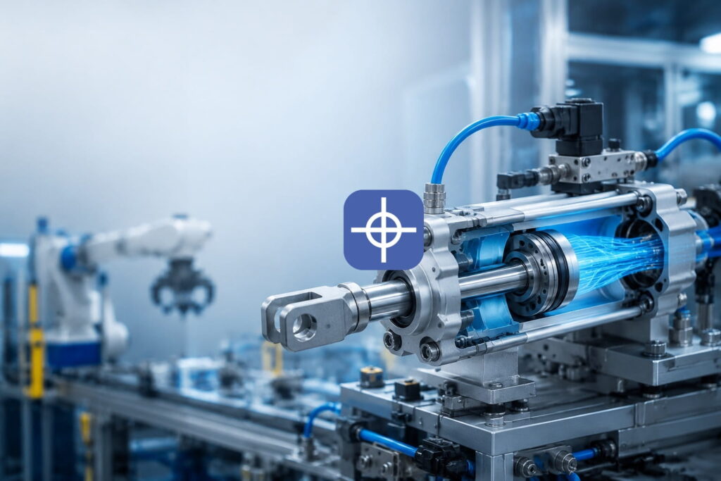
Cutaway view of a pneumatic cylinder, showing the piston, rod, and internal seals.
Why Is the Pneumatic Cylinder Important in CNC?
In CNC machines, accuracy, speed, and safety are critical. The pneumatic cylinder meets these needs by using compressed air, which is cheap and readily available. Unlike hydraulic systems, which use oil, pneumatics is cleaner and safer, though it can be limited at high force levels. Its main application is in workholding, which can increase productivity by 30-50%. For example, in the automotive industry, pneumatic cylinders are used to clamp sheet metal in order to reduce vibration.
⚠ A photo originally placed here has been omitted — see the note at the end of this document.
Structure of the Pneumatic Cylinder
The structure of the pneumatic cylinder is simple but efficient. The main components are as follows:
Cylinder Barrel: The main housing, usually made of steel or aluminum to withstand pressure.
Piston: The moving part that air pushes against to create motion.
Piston Rod: Connected to the piston and transmits the linear force.
End Caps: Close off the two ends of the cylinder and contain the air inlet/outlet ports.
Seals: Prevent air leakage, usually made of elastic materials such as rubber.
Cushions: Reduce impact at the end of the stroke.
Guides and Bearings: Ensure smooth movement of the rod.
Structure Diagram of the Pneumatic Cylinder:
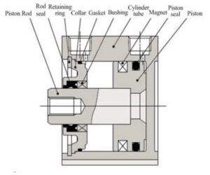
Labeled cross-section: piston rod, rod seal, retaining ring, collar, gasket, bushing, cylinder tube, magnet, piston seal, and piston.
Note: In CNC, a compact structure is preferred for small spaces.
Types of Pneumatic Cylinders
Pneumatic cylinders are classified based on their function and design:
| Type | Description | Application in CNC | Advantages | Disadvantages |
| Single-Acting | Air pushes in one direction; a spring returns it | Simple part clamping | Simple and inexpensive | Force limited to one direction |
| Double-Acting | Air creates motion in both directions | Tool changing and doors | Precise control, high speed | Requires a more complex air system |
| Rodless | Motion without an external rod, using a magnetic band | Limited spaces on the CNC table | Saves space | Less force |
| Compact | Short length with high force | Small CNC machines | Suitable for tight spaces | Limited stroke |
| Rotary | Produces rotary motion | Table indexing | Angular accuracy | More complexity |
| Guided | Has internal guides for accuracy | Precision clamping | Prevents deflection | Higher cost |
Selection is made based on ISO standards such as ISO 15552 (for profile cylinders). In CNC, the double-acting type is common because two-way motion is essential for automation.
Working Principle of the Pneumatic Cylinder
Air Compression: A compressor compresses the air (4-10 bar) and it is stored in a tank.
Air Entry: Air enters one side of the cylinder through a control valve and moves the piston.
Linear Motion: The piston moves the rod and generates force (F = P × A, where P is pressure and A is the piston area).
Air Exit: Air is expelled from the other side.
Return: By spring in the single-acting type, and by reverse airflow in the double-acting type.
Note: In CNC, this principle is used for clamping: air opens the clamp, the part is placed, and then it closes. Speed can reach 1-2 meters per second, but pressure fluctuations require a regulator.
Applications in CNC
Workholding: Uniform force for holding the part in place, such as a pneumatic vise.
⚠ A technical drawing originally placed here has been omitted — see the note at the end of this document.
Tool Changing (ATC): Fast movement of tools in the spindle.
Opening and Closing Doors: Increases safety and cycle speed.
Part Ejection: Transfers finished parts to the conveyor.
In industries: Automotive (sheet cutting), aerospace (complex parts), medical (implants).
Note: In smart systems, sensors monitor the force.
Advantages and Disadvantages
Advantages:
High response speed (milliseconds).
Low installation and maintenance cost.
Lightweight and compact.
High safety (no flammable fluid).
Energy efficient (air can be recovered).
Flexibility for different sizes.
Disadvantages:
Less force compared to hydraulics.
Sensitive to pressure fluctuations and contamination.
Noise and the need for a compressor.
High initial cost for smart systems.
A filter is essential in dirty environments.
Compared with hydraulic cylinders, pneumatic cylinders are better suited to fast operations.
Step-by-Step Installation
Choose the Location: Place the pneumatic cylinder on the CNC’s linear axis, aligned with the part.
Cleaning: Clean the surface so contamination doesn’t get in.
Securing: Fasten it with screws and a bracket (check the correct torque).
Air Connection: Connect the ports to the air hose, and use a regulator for constant pressure.
Alignment: Make sure the rod moves without deflection.
Testing: Introduce air and check the motion; inspect for leaks.
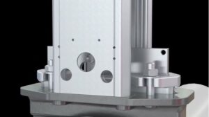
Close-up of a pneumatic cylinder mounted and aligned on a machine base.
Maintenance and Repair
Regular maintenance can extend the pneumatic cylinder’s service life to millions of cycles.
Maintenance Steps:
Daily Inspection: Check for air leaks, noise, or sluggish movement.
Cleaning: Replace filters and dryers monthly so moisture doesn’t get in.
Lubrication: Use pneumatic oil for the seals.
Seal Inspection: Replace if damaged (turn off the system first).
Alignment: Check the rod for wear.
Sensors: In smart systems, analyze data to predict failures.
Repairing Common Problems:
Sluggish Movement: Check the pressure; enlarge the control line.
Leakage: Replace the seals.
Pulsing: Reduce the side load.
Corrosion: Use resistant materials such as stainless steel.
Note: If the damage is severe, replace the pneumatic cylinder entirely.
Conclusion
Pneumatic cylinders have brought about a major transformation in CNC, and with their accuracy, speed, and low cost, they strengthen automation. Choosing the right type and performing regular maintenance ensures optimal performance. As technology advances, their role in smart manufacturing will continue to grow.
Smart cylinders with IoT sensors for real-time monitoring and predictive maintenance are currently under development, and in the CNC systems of the future, integration with robotics will make fully automated operation possible.
References
- https://gimbelautomation.com/blogs/news/pneumatic-cnc-workholding-solutions-everything-you-need-to-know
- https://www.compactautomation.com/education/compact-by-design/pneumatic-cylinders-a-comprehensive-guide
- https://www.cncprog.com/pneumatic-cylinder-partsworking-principle-and-hsn-code/
- https://www.blpneumatic.com/news/essential-benefits-of-pneumatic-cylinders/
- https://cylindersinc.com/blog/pneumatic-cylinders-repair-and-maintenance-guide
- https://www.youtube.com/watch?v=hmz1h5fk2bI
- https://pneumaticmfg.com/blog/understanding-pneumatic-cylinders/
- https://cncontrolvalve.com/a-comprehensive-guide-to-pneumatic-control-systems/
- https://www.cnccookbook.com/cnc-jigs-fixtures-workholding-solutions-milling/
Author: Mahboubeh Sajjadi
For industrial implementation, explore Radonix PC-based CNC controllers, control software and machine-specific HMI systems. Radonix PC-based CNC controller systems.