
Table of Contents
- Introduction: What Is RTCP in CNC?
- Why Does 5-Axis Machining Need RTCP?
- How RTCP Works, in Simple Terms
- What Exactly Does RTCP Do?
- Advantages of RTCP in 5-Axis Machining
- RTCP from the Machine’s Kinematic Perspective
- How Is RTCP Activated in Different Controllers?
- RTCP Calibration and Setup
- Important Industrial Applications of RTCP
- The Difference Between a 5-Axis Machine With and Without RTCP
- Common Challenges and Errors in Using RTCP
- Conclusion
- References
1. Introduction: What Is RTCP in CNC?
RTCP stands for Rotation Tool Center Point, and in five-axis CNC systems it means “control of the tool’s center point during rotation,” also known as Tool Tip Follow. In other words, as the rotary axes such as A, B, or C turn, the controller compensates the movement of the linear axes so that the tool tip (TCP) always stays on the programmed path. On a five-axis machine without RTCP, when the rotary axes turn, the tool tip drifts off the intended path, and the programmer has to account for these shifts in post-processing or even manually. It performs these calculations simultaneously and automatically inside the controller.
2. Why Does 5-Axis Machining Need RTCP?
On three-axis machines, the tool only moves along the X, Y, and Z axes, and calculating the tool tip’s path is relatively simple. On five-axis machines, however, in addition to the three linear axes, two rotary axes, usually A/B/C, are also involved. Combining linear and rotary motion causes:
- The actual tool tip path to become a complex, non-linear curve
- Every small change in the angle of the spindle head or table to affect the tool tip’s position
- A so-called Non-linear Error to appear between the theoretical path in CAM and the actual path on the machine
RTCP tries to reduce this error in real time by calculating the machine’s kinematic model and compensating for axis motion.
3. How RTCP Works, in Simple Terms
To understand this better, suppose:
- In the CAM software, the tool path is defined based on the workpiece coordinate system (WCS)
- Your machine is a five-axis machine with a rotary table, for example with the A and C axes
- When the table rotates, the part effectively rotates in space, and the tool tip’s coordinates relative to the machine change
Now we have two cases:
Case Without RTCP
- CAM must calculate the tool tip’s path from the start, taking the machine’s actual kinematics into account
- The post-processor must account for the necessary X/Y/Z shift for every change in the A/B/C angles
- If the tool length or the pivot point (the spindle head’s rotation axis) changes, the post-processing usually has to be redone
Case With RTCP Active
- CAM only provides the TCP’s direction and position relative to the part (Tool Vector + TCP)
- Based on the machine’s kinematic model, the CNC controller itself calculates, for this tool tip position and direction, how far the linear axes X/Y/Z need to move and what angle the rotary axes A/B/C need to take
- If the tool length changes, all you need to do is correct the tool length in the tool table; the system compensates for the rest
4. What Exactly Does RTCP Do?
In summary, it performs three key tasks in five-axis machining:
Keeping the tool tip fixed on the programmed path, even while the rotary axes are moving. At every instant, the controller calculates and corrects the tool tip’s true location based on the axis angles.
Automatically compensating for changes in tool and part angle. When the part rotates on the turntable, the part’s coordinate system shifts relative to the machine; it accounts for this shift and makes it behave as if the coordinate system is always attached to the part.
Removing the need for complex post-processing calculations. Post-processing becomes simpler, since it no longer has to perform all the kinematic transformations itself. Many controllers let you activate it with commands such as #RTCP ON/OFF or through Transform/TRAORI options.
5. Advantages of RTCP in 5-Axis Machining
5.1 Increased Dimensional Accuracy and Surface Quality
- Because axis motion is compensated for instantaneously, the tool tip’s actual path stays very close to the path planned in CAM
- Errors caused by the combined motion of the rotary and linear axes (Non-linear Error) are noticeably reduced
- On free-form surfaces (molds, impellers, implants, turbines, 3D profiles), surface quality is better, with less waviness
5.2 Increased Productivity and Reduced Setup Time
Without RTCP, every tool change, fixture change, or even coordinate correction has to be redone in CAM/post-processing.
- With RTCP, you can simply correct the tool length in the table
- Offsets and compensations are applied online
- Setup and tuning time is much shorter
5.3 Simpler Programming and Greater Flexibility
- The programmer works mostly with the geometric path and the tool’s angle relative to the surface rather than the machine’s kinematics
- If you switch machines, for example from a Head/Table configuration to Table-Table, you simply apply the new post-processor and its settings; the part program does not necessarily need major changes
5.4 Enabling Advanced Machining Strategies
- Machining strategies where the axes are in continuous, simultaneous motion (Simultaneous 5-Axis) are, in practice, nearly impossible or very risky without RTCP
- It allows the actual feedrate on the surface to stay nearly constant and reduces vibration and impact
The Huazhong controller’s “5-Axis Linkage RTCP Function” diagram focuses exactly on this topic. It shows both the kinematic structure (the several rotary axes) and, on the left side of the figure, the rotation axes and the Tool Center Point.
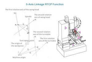
Huazhong controller’s 5-Axis Linkage RTCP Function: kinematic structure, rotation axes, and Tool Center Point.
6. RTCP from the Machine’s Kinematic Perspective
To implement this capability, the controller must:
- Know the machine’s kinematic model: the machine type, such as Head-Table, Table-Table, or Head-Head; the axis order, for example X-Y-Z-A-C or X-Y-A-C-Z; and the precise distances between reference points, such as the pivot point, the table’s center of rotation, and the mechanical zero point.
- Solve the mathematical coordinate-transformation model: the transformation between the workpiece coordinate system (WCS) and the machine coordinate system (MCS); the conversion of A/B/C rotations into rotation matrices and then into linear X/Y/Z movements.
- Process every G-code block: read the tool direction vector and the TCP position from the program; calculate new coordinates for all axes based on the current axis angles; adjust the interpolation motion so that the TCP path stays smooth, continuous, and accurate.
7. How Is RTCP Activated in Different Controllers?
The name and activation method differ across CNC brands, but the underlying concept is the same:
- Heidenhain: Typically through concepts such as TCPM, PLANE SPATIAL, and specific parameter settings.
- Siemens: Uses transformations such as TRAORI to activate tool tip compensation in 3D space.
- Beckhoff / TwinCAT CNC: Commands such as #TRAFO ON and #RTCP ON to activate 3D tool compensation.
- 5-Axis Router and industrial machining-center controllers: In the machine specifications, an RTCP Option or 5-Axis version of this feature is usually listed as a separate, paid capability, meaning not every five-axis machine necessarily has this capability.
8. RTCP Calibration and Setup
This capability depends on the accuracy of the kinematic model; therefore, precise calibration is the main condition for correct operation:
- Precisely measuring the distance from the rotary axes to the tool tip: terms such as Pivot Length and Pivot Offset in the parameters.
- Calibration using a ball, probe, or standard test piece: some manufacturers, such as SCM, offer ready-made systems for this calibration process that the end user can perform themselves, so that official service does not need to be called in for other small errors.
- RTCP motion tests: running specific patterns (a dedicated test path) to check whether the tool tip actually stays on a single point or path as the angles change.
If this calibration is not performed correctly, it can create errors instead of helping.
9. Important Industrial Applications of RTCP
It is used mainly in industries that have complex 3D parts, where surface and dimensional accuracy are very important, and where the number of set-ups needs to be kept low.
Examples:
- Aerospace and Turbine Industry: Turbine blades, impellers, 3D airflow channels; machining undercuts and hard-to-reach areas.
- Mold & Die Making: Plastic molds, die-casting molds, high-pressure molds; it allows a mold to be machined from different angles in a single setup.
- Medical and Implants: 3D bone implants, artificial joints; the need for high surface accuracy and repeatability.
- Wood, Stone, and Composites: On 5-axis routers, carving statues, figures, furniture parts, 3D headstones, and so on; it makes it possible to properly control the tool’s height and angle on curved surfaces.
10. The Difference Between a 5-Axis Machine With and Without RTCP
Without RTCP: More complex programming; requires a dedicated, precise post-processor for each machine; high sensitivity to changes in tool length; in practice, better suited to 3+2 (positioning) machining than true simultaneous 5-axis.
With RTCP: The programmer focuses mainly on the part’s geometry and the cutting strategy; true full 5-axis simultaneous machining becomes usable; high flexibility in tool and fixture changes; better final surface finish and higher reliability at high feedrates.
11. Common Challenges and Errors in Using RTCP
Although this technology has many advantages, in practice you will run into the following challenges:
- Incorrect or Incomplete Kinematic Model: If the distances and angles are defined incorrectly, the compensation will also be wrong, and the errors will get worse.
- Incomplete Calibration: Not using motion tests or standard test pieces allows systematic errors to remain hidden.
- Poor Matching Between CAM and the Controller: CAM assumes the controller works with a specific model in this mode; if the controller’s settings or active axes don’t match this assumption, the result will be unsatisfactory.
- Axis Speed and Dynamics Limitations: If the servo dynamics are not well tuned, at high feedrates the five axes may not be able to accurately follow the path, and the contour error can increase.
12. Conclusion
In summary, in the world of five-axis CNC, RTCP is a kinematic compensation technology at the CNC controller level that keeps the tool tip on the programmed path while the axes move simultaneously; it increases accuracy and surface quality, and reduces setup time and programming complexity; and for correct operation, it requires an accurate kinematic model, proper calibration, and coordination between CAM, post-processing, and the controller settings.
13. References
- Fan, S. T., et al. “RTCP Function in Five-Axis Machining.” Key Engineering Materials journal, 2011.
- Wang, F., et al. “Design and implementation of five-axis transformation function based on CNC kernel.” Mechanical Systems and Signal Processing / Chinese Journal of Aeronautics (ScienceDirect), 2014.
- “On the workpiece setup optimization for five-axis machining with RTCP function.” A research paper on using RTCP for workpiece setup optimization and the Tool Tip Follow / TCPM concept.
- Beckhoff — Rotation Tool Center Point (RTCP) — TwinCAT CNC Programming. Beckhoff’s official documentation for RTCP, showing how to select the kinematics (#KIN ID) and activate RTCP with #TRAFO ON, along with a G-code example.
- Siemens — Manual 5-axis machining / TRAORI. The SINUMERIK documentation (PDF) explaining the TRAORI option as a 5-axis, tool-tip-control function, and showing how the control handles kinematics and tool offset in RTCP mode.
- Heidenhain — TCPM / 5-Axis Machining (TNC 640, iTNC 530, TNC7). The “Master the Power of Five Axes” brochure and TNC documentation explaining the TCPM (Tool Center Point Management) function and its role in tool tip control and simultaneous 5-axis machining.
- FANUC — G43.4 / G43.5 RTCP Type II.
Author: Nima Rad