Controller hardware
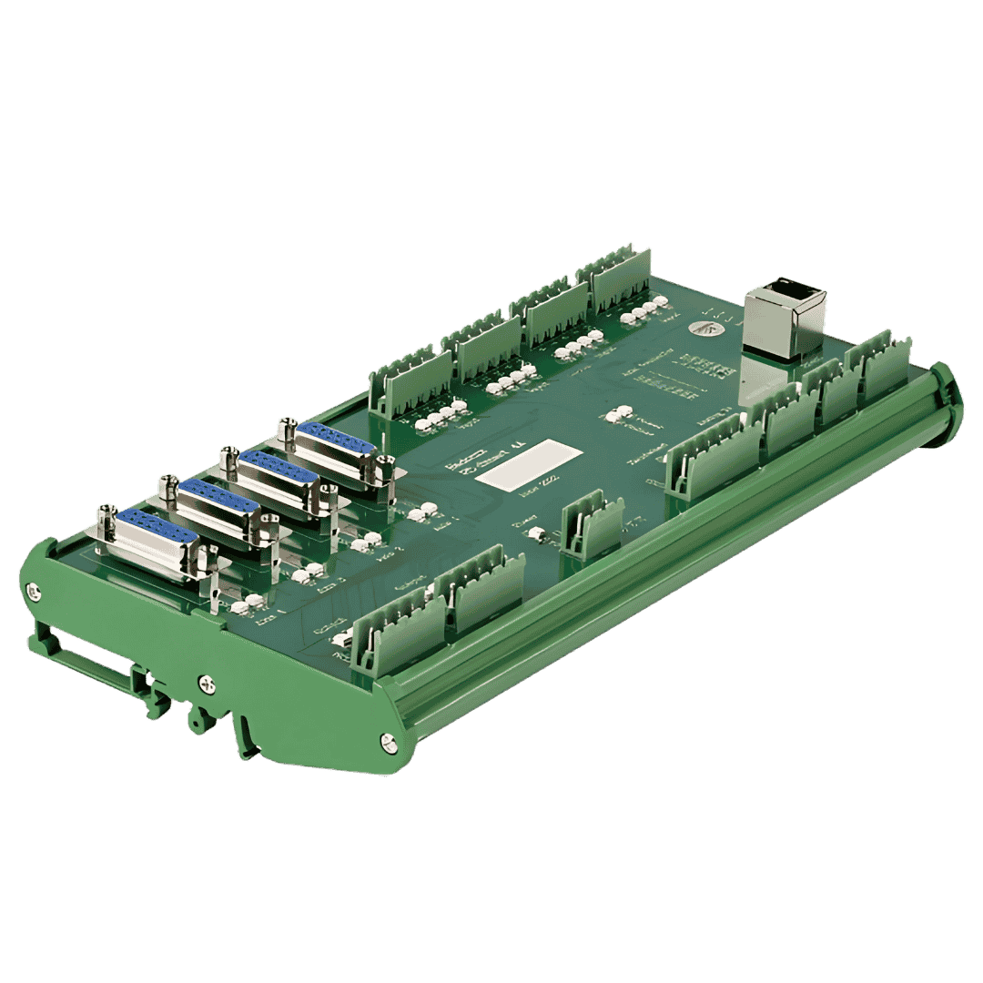
Industrial PC-based motion controllers for servo and stepper systems, with configurable digital and analogue machine signals.
Explore RADONIX hardware

CNC CONTROL FOR MACHINE MANUFACTURERS
A practical technical guide to the RADONIX platform - controller hardware, machine-control software, configurable I/O and a machine-specific HMI engineered to work as one system.
ONE COORDINATED PLATFORM
RADONIX provides a complete, configurable CNC control solution for machine manufacturers. The platform combines three coordinated layers that can be adapted to the machine application and operating process.
Industrial PC-based motion controllers for servo and stepper systems, with configurable digital and analogue machine signals.
Explore RADONIX hardwareProgramme preparation, simulation, motion execution, I/O mapping, diagnostics and production workflow tools.
Explore CAM-Pro softwareA dedicated user interface designed around the axes, alarms, sensors, tooling and operating sequence of the machine.
Explore machine interfacesRADONIX Smart and PC-Pro LAN controllers connect to the computer through a LAN network and command compatible servo or stepper drives using Pulse and Direction signals. The current range provides standard control for 2 to 6 independently controlled and interpolated motion axes, depending on the controller model. In specialised multi-motor applications such as jewellery machines, X4 boards can distribute one axis command to multiple motors and provide around 12 physical motor channels without increasing the independent axis count.
CONTROL ARCHITECTURE
The current RADONIX generation operates as an open-loop system at the CNC controller level. This does not prevent a compatible servo drive and servo motor from operating as their own closed-loop servo system.
CNC CONTROLLER LEVEL
RADONIX calculates the required position and sends the motion command to the connected drive. The current controller does not directly receive encoder position or verify that the physical axis has reached the commanded position.
SERVO SYSTEM LEVEL
The encoder returns the actual motor position to the servo drive. The drive compares actual and commanded position and corrects the motor-position error internally.
The main requirement is a drive that accepts a Pulse and Direction command input. RADONIX can work with stepper drives and servo systems using:
The encoder type and communication among encoder, motor and drive are managed by the servo system and do not interfere with the current RADONIX controller.
RADONIX software can process commanded positions with calculations of up to 12 decimal places. Actual machine accuracy also depends on:
MOTION AND PROGRAMME EXECUTION
Motion parameters can be tuned for individual axes and the complete toolpath, allowing the control behaviour to follow the required machine dynamics and machining quality.
These parameters allow motion behaviour to be adjusted according to the mechanics of the machine and the required finish quality.
RADONIX supports standard G-code execution, programme control, line selection, toolpath display and starting from a selected line. Compatible HMIs can also process DXF files directly, including:
This can simplify two-dimensional cutting, routing, engraving and jewellery workflows.
After an interruption, the operator does not normally need to restart the complete programme. RADONIX can retain programme information and continue from a selected G-code line.
The software can recover relevant states such as tool number, spindle commands and previous M-code conditions before restarting.

MACHINE I/O AND AUTOMATION
Predefined input and output functions can be assigned directly in many standard applications, reducing the need for complex macro programming.
Configure machine feedback and operating commands such as:
Switch external equipment through relays, contactors, valves and related devices:
Each output can be configured around the actual machine process and operating logic.
The software can activate an output, wait for confirmation from a position sensor and only then continue to the next stage. Typical uses include:
Supported hardware configurations can receive or send variable signals for:
The signal type and voltage or current range depend on the selected controller or analogue module.
RADONIX can monitor Emergency, Alarm, Hold, Home, Limit and machine-ready conditions, and can activate outputs according to defined axis-position zones. These software interlocks must be used together with an appropriate hardwired safety circuit.
COMMISSIONING AND MACHINE SETUP
Configure each axis with its own homing direction, speed, sequence and offset. Gantry machines with two motors on one axis can use two independent Home sensors so each side is referenced separately and the bridge is aligned during homing.
Soft travel limits can prevent movement outside the permitted working area.
Z-Probe and tool-measurement functions can detect the workpiece surface, set the Z zero point and measure tool length.
In supported applications, multi-point surface scanning can compensate for surface variation - particularly for engraving and machining uneven surfaces.
CUSTOMISED USER INTERFACE
The RADONIX HMI can be configured for the actual machine application instead of forcing operators to use a complicated general-purpose CNC screen.
Machine manufacturers can define:
NEXT-GENERATION CONTROLLER
LEGO is designed for more complex machines, multi-axis production systems and advanced industrial applications. The architecture is intended to provide greater scalability, processing capacity and access to more information from compatible servo drives.

| Capability | Smart and PC-Pro LAN | LEGO |
|---|---|---|
| Controller network | LAN connection to the industrial PC | EtherCAT-based architecture |
| Motion-axis capacity | 2 to 6 axes, model-dependent | Up to 16 axes |
| Drive architecture | Pulse and Direction command; controller open loop at CNC level | Designed for more servo-drive information and advanced control |
| Digital I/O | Controller and module dependent | Up to 64 inputs and 64 outputs |
| Parallel processing | Standard machine-control applications | Up to 4 simultaneous tool paths |
| Status | Current product generation | Final testing before market release |
DISCUSS YOUR MACHINE
For a useful first review, include the number of axes, servo or stepper drive models, required digital and analogue I/O, machine application and special functions such as ATC, dual-axis homing, THC or multi-head control.
RADONIX CAM-PRO · PC SMART · PC-PRO
Radonix CAM-Pro and Radonix CNC control software for compatible PC Smart and PC-Pro controllers can handle and execute G-code programs containing 5 to 10 million lines.
Bring large CAM-generated toolpaths into your CNC control workflow for detailed routing, engraving, 3D machining and other complex production jobs.
Explore CAM-Pro large-program capability →Related CNC controller expertise