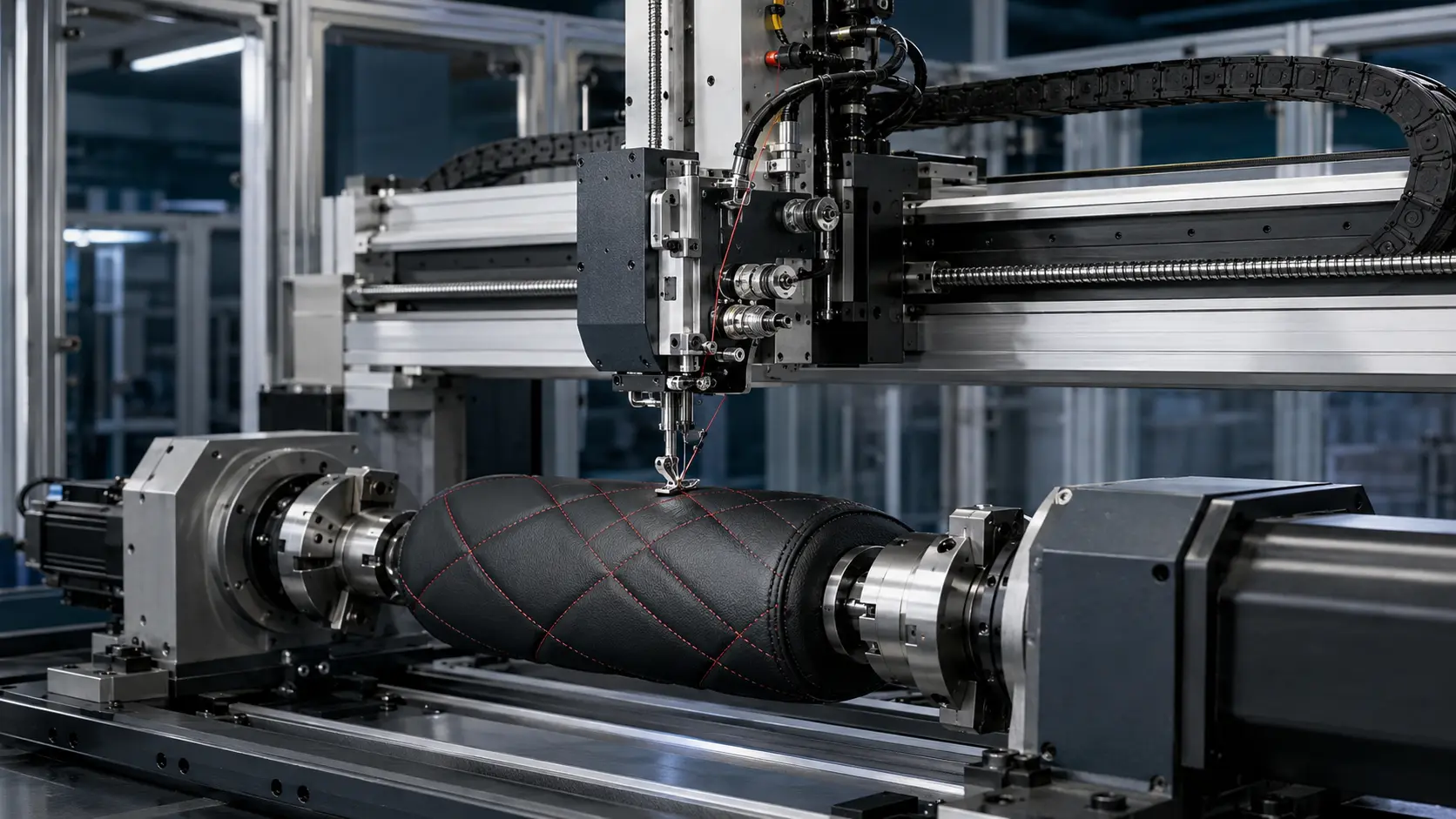
Radonix for Textile — Knife and Sewing Edge-of-Technology CNC

A complete, production-ready stack of hardware + software for slab cutting, profiling, drilling, polishing, and waterjet. Built on Radonix PC-Smart / PC-Pro controllers and process-specific interfaces.

Radonix for Textile & Knife CNC

Radonix brings a single, scalable platform for Textile machining: PC-Smart 4A / PC-Pro LAN 4A/6A controllers, process-specific interfaces (XYC Knife Cutter , XYRS Sewing). From countertops and sink cutouts to mitered edges and 5-axis profiling, Radonix emphasizes clean edges, safe operation and fast setup.

Direct DXF run, parametric shapes (stairs, arcs, circles/slots) Disk-tool optimization (diameter, thickness, offsets, Z-slow)

  • Waterjet control with fine speed/accel for crisp edges
  • Camera slab mapping with 1:1 placement & vein alignment
  • 2D/3D preview, start-from-shape and recovery tools
  • AnyDesk remote setup & diagnostics

Typical Outcomes

  • Faster job prep: import → place on slab → simulate → cut
  • Chip-free edges via tuned feeds/accelerations and Z-slow
  • Accurate sink & hob cutouts with templates and probing
  • Reliable miters & bevels with safe angles and passes
  • Higher yield using camera-assisted nesting on remnants

Solution Lineup for Stone & Marble

Five interfaces cover slab cutting, profiling, 5-axis miters/profiles, waterjet, and rotary work.

1) XYC Knife Cutter

3-axis cutting, profiling and drilling. Ideal for countertops, tiles and panels.

  • Supports disk tools, milling heads, core drills
  • Direct DXF; nesting, array, mirror, scale, rotation
  • Z strategies: depth per pass, Z-slow, safe retract
  • I/O: water/pump, vacuum, spindle/VFD, safety

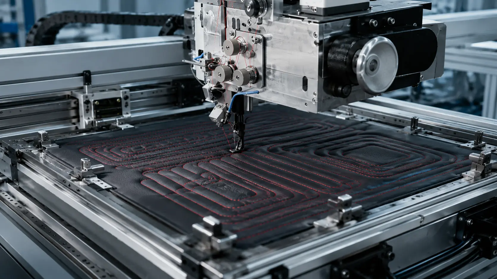
3) XYR Sewing

Full interpolation for complex miters, bevels and freeform profiles.

  • 5-axis control (XYZ + C + A) with disk optimization
  • Variable angle miters, profiling, undercuts (machine-limited)
  • Library: stairs, arcs, circles/slots, sink/hob cutouts
  • 2D/3D simulation & collision checks

5) XYZA Rotary Stone

4-axis carving and cylindrical profiles for columns and statues.

  • Simultaneous XYZ + A; indexed or continuous
  • Diameter setup, per-pass advance, finish smoothing
  • Tailstock/steady rest I/O; probe for zero setting
  • Dust/water control and safety interlocks

2) XY Sewing

Bridge-saw style rotation for arc cuts, slotting, and angle setting.

  • C-axis rotation with disk diameter/thickness compensation

  • Straight/arc cuts, pockets, slot/circle features

  • Miter & bevel presets with safe approach/exit
  • Camera placement for precise slab alignment

4) XYRS Sewing

High-precision waterjet cutting with efficient path planning.

  • 3-axis interpolation with fine speed/accel control
  • Direct DXF; lead-in/out, tabs, corner slow-down
  • Pause, reverse, resume; start from any entity
  • I/O: pump, abrasive, water valves, safety interlocks

5) XYZA Rotary Stone

4-axis carving and cylindrical profiles for columns and statues.

  • Simultaneous XYZ + A; indexed or continuous
  • Diameter setup, per-pass advance, finish smoothing
  • Tailstock/steady rest I/O; probe for zero setting
  • Dust/water control and safety interlocks

What the Disk Interface Does

The Disk interface drives a rotating saw blade for straight, angled, and curved cuts on stone slabs—coordinating XYZ linear axes with C (blade yaw/rotation) and A (blade tilt). It fuses machine kinematics, tool compensation (blade Ø / thickness), and shop-floor I/O (water, pneumatics, safety) into one operator-friendly HMI.

Knife CNC Machine

What Is Automatic Digital Cutting Machine (CNC Knife Cutter)?

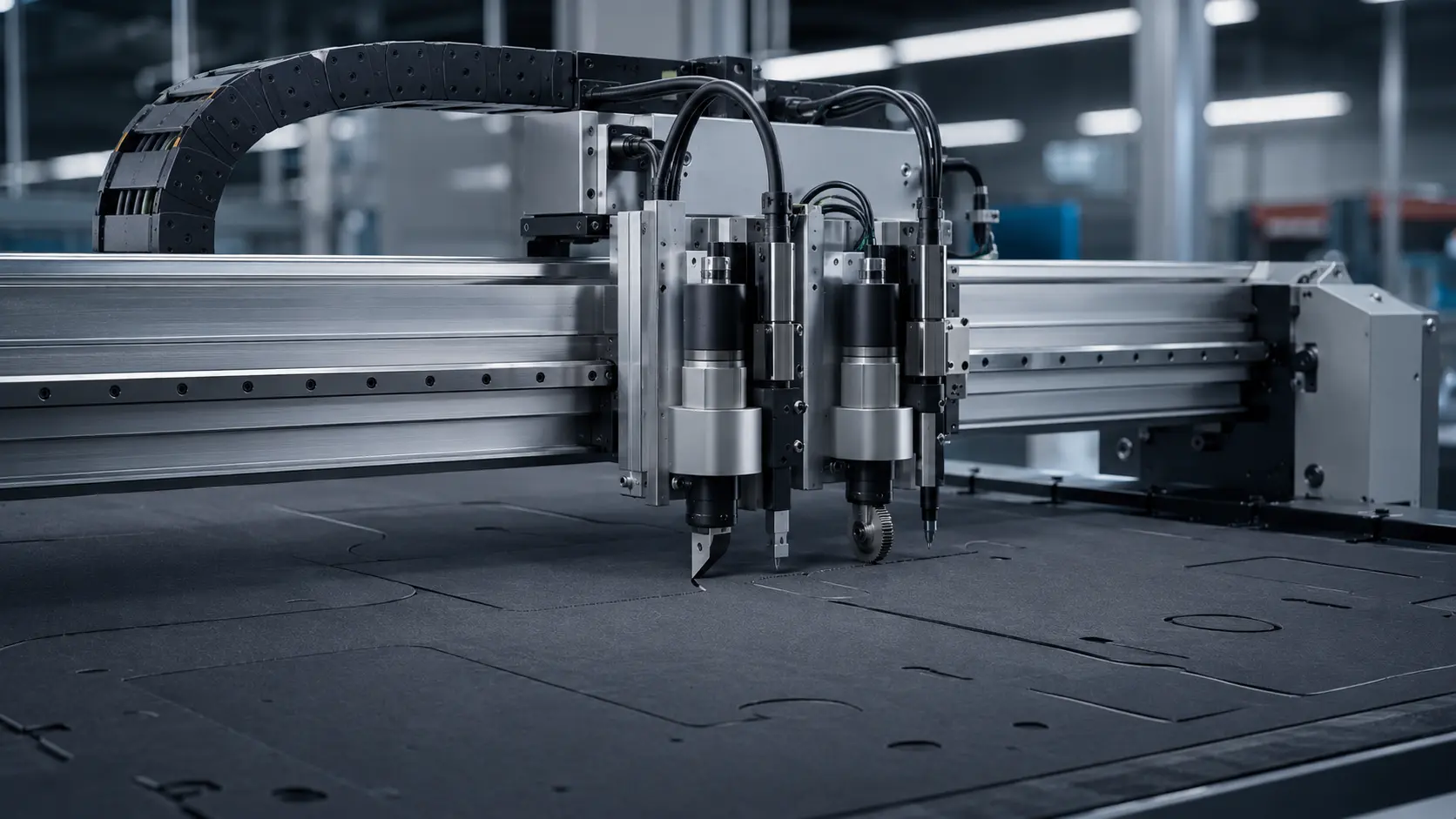
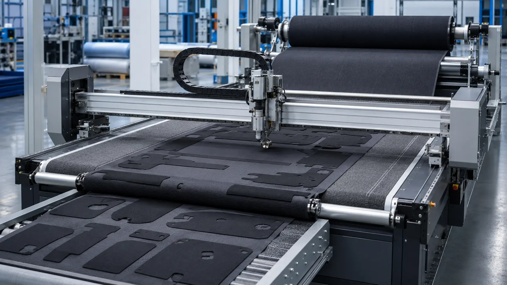
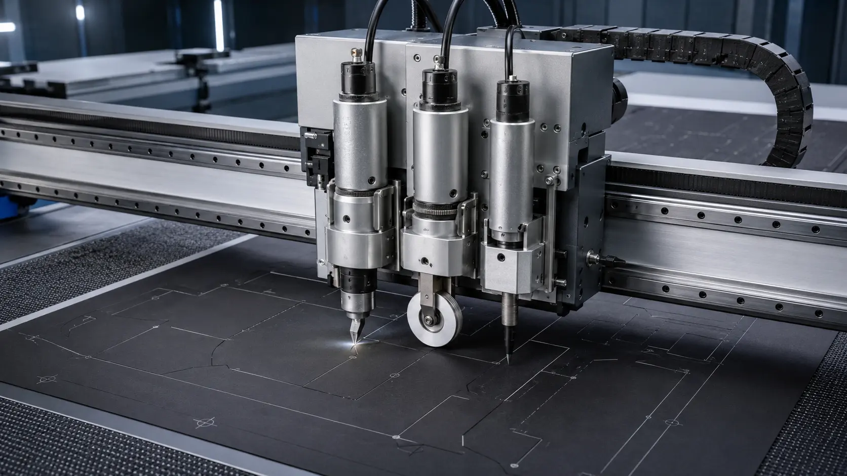
Automatic digital cutting machine (also known as CNC knife cutter) is a type of automated precision cutting system with CNC (Computer Number Controlled) controller which is used for high-precision cuts of heavier flexible and semi-rigid materials. It works with the multi-tool blades consisting of vibration knife, oblique knife, circular knife, punching knife, milling knife, punch roller, or marking pen. CCD camera and projector are optional for more precise cuts.

A automatic digital cutter is also known as digital cutting table, automatic flatbed cutter, cutting plotter, dieless cutter, flash cutter, CNC knife cutter, CNC drag knife, CNC tangential knife, CNC oscillating knife, automatic precision cutter, and CNC blade cutting table.

A drag knife can be assembled on your CNC router or spindle collet to cut fabric, leather and vinyl.

At home, outdoors, on vacation, in the streets, in a car or on an airplane – we are constantly surrounded by products likely to have come off a STYLECNC automatic digital cutter or cutting plotter. From street signs to storefronts, packaging to spacesuits, hot-air balloons to bullet-proof vests, airplane seats to windshields, STYLECNC’s automatic digital cutters can cut all of the materials involved with the perfect tool for your project.

How Many Types of Automatic Digital Cutters?

Digital cutting machines are divided into digital gasket cutter, carpet cutter, fabric cutter, leather cutting tool, cardboard cutter, foam cutting system, paper cutter, film cutting tool, vinyl cutter and fiberglass cutting system.

What Are CNC Digital Knife Cutting Machines Used For?

CNC digital knife cutters are used for the cuts of special-shaped graphics made of non-metallic flexible materials. It can quickly complete various processes such as full-cut, half-cut, milling, perforate, crease and mark, solving the problems of special-shaped picture cuts, improving production efficiency, and reducing labor cost. It can reduce the defect rate caused by manual tool errors, help users complete high-quality cuts faster, more stable, and more accurately at low cost, improve user market competitiveness, and seize more market shares. Digital flatbed cutters are used in advertising packaging, clothing and footwear, automotive interiors, luggage, composite materials and other industries.

Graphics Industry

Applications: Outdoor advertising, displays, traffic signs, fleet graphics, exhibits, illuminated signage, store décor, decals, floor graphics, etc.

References: 3M, Airbus, Avery Dennison, Christinger, Fair-play, Fastsigns, Graphics Gallery, Imaba, Lufthansa, netService, PlotFactory, Quarmby Colour Studio, Sin Fung Advertisement, Stylographics, Supersine Duramark, Zebra Graphics, etc.

Packaging Industry

Applications: Printed or unprinted packaging, POP/POS displays, foam inserts, dies making.

References: Beiersdorf, Chesapeake, Edelmann, Hasbro Toys, Heidelberg, International Paper, Long Chen Paper, Mauro Benedetti, Mondi, Packaging Cooperation of America (PCA), Panther Packaging, Philip Morris, sanovi aventis, SCA,Seda, Smurfit Kappa, STI, TetraPack, Thimm Verpackung, Triwall, etc.

Leather Industry

Applications: Shoes, garments, upholstery, handbags, briefcases, car and airplane seats, etc.

References: Adidas, Akris, Bally, Cavallo, Clarks, Ecco, Gabor, Geox, Gucci, Louis Vuitton, Nike, Prada, Puma, Recaro, Rolf Benz, Samsonite, de Sede, Sergio Rossi, Timberland, etc.

Textile Industry

Applications: Garments, upholstery, airbags, flags, sun shades/umbrellas, car and airplane seats, etc.

References: BMW, Diesel, Ford, Hugo Boss, Interstuhl, Jil Sander, Joop, Levi Strauss, Mercedes, Triumph, Volkswagen, Zodiac, etc.

Composite Industry

Applications: Defense, functional textiles, rotor blades for wind wheels and helicopters, aircraft and automotive parts, etc.

References: 3C-Carbon Composite Company, ACE, Airbus, Audi, Bell Helicopter, BMW, Carbo Tech, DLR, Dyneema, Eurocopter, FACC, Ferrari, McLaren, Pilatus, Red Bull Racing, Scuderia Toro Rosso, SGL Group, ThyssenKrupp, etc.

Techtex Industry

Applications: Truck tarpaulin, carpets, awnings, hot-air balloons, sails, outdoor equipment, inflatable boats, etc.

References: Badertscher, Barrisol, Bieri, Daedler, de Sede, Eschenbach Zeltbau, Estrella Betten, Höcker HTS Structures, interstuhl, Kusch+Co, Quelli In Luce, Ruckstuhl, Sachsen Fahnen, W.Schillig, etc.

Specialty Applications

Applications: Adhesives, gaskets and filter materials, PVB film for auto glass, architectural models, foam, wood veneer, floor coverings, film for solar and photovoltaic systems, aluminium foil, watch faces, etc.

References: ABB, Daimler Chrysler, Dell, Ferrari, Herzog & De Meuron, LG Electronics, Pilkington, Porsche, Procter & Gamble, Red Bull F1-Team, Rolex, SaintGobain Sekurit, Samsung Electronics, Swatch, etc.

CNC Digital Knife Cutting Table Advantages

1. High speed with high quality, its cutting speed is 5-8 times faster than laser cutter.

2. Advanced computerized CNC control system, which is easy to operate with ethernet port.

3. Working without air pollution, no burnt edge, uniform in color.

4. It can cut soft materials with perfect edges and corner.

5. It adopts Japan YASKAWA servo motor and drive, fast speed with high precision.

6. It can be equipped with different knife tools & blades to meet a variety of needs.

7. Special safety sensing device meets the European standard.

8. Intelligent tabletop mapping.

9. Automatic tool calibration.

10. Multi-task repeat cutting, intelligent absorption.

Automatic Digital Cutter Features

1. Using vibratory knife cutting technology, save the cost and time of knife manufacturing, management, storage, etc. in the production and development process, bid farewell to the traditional manual knife cutting process, break the traditional mode of relying on workers for production, and take the lead in entering the era of digital mold making .

2. Multi-functional cutting head design, multiple sets of highly integrated processing tools, which can be used as a working unit for interactive cutting, punching and marking operations.

3. Difficulty, complicated patterns, template removal that cannot be achieved by tool molds, substantial expansion of the design space of shoe designers, creation of new models that cannot be copied manually, making templates attractive, making the design truly achievable, and not afraid of not being able to achieve it. field of.

4. For well-functioning emissions, the calculation system performs automatic emissions, accurately calculates, calculates costs, and accurately manages material distribution, and actually realizes a digital zero inventory strategy.

5. Through projector projection or camera shooting, grasp the leather outline and effectively identify leather defects. In addition, according to the natural pattern of the leather, the cutting direction can be adjusted randomly to increase output, reduce loss, and increase the effective utilization of materials.

6. Procedural computer simulation can eliminate the interference of workers’ emotions, skills, fatigue and other personal factors on the existing supply, prevent hidden waste, and improve the use of materials.

How To Buy An Automatic Digital Cutter?

1. Consult:

We will recommend the most suitable CNC digital cutting table to you after being informed by your requirements.

2. Quotation:

We will offer you with our detail quotation according to the consulted digital cutting system. You will get the most suitable specifications, the best accessories and the affordable price.

3. Process Evaluation:

Both sides carefully evaluate and discuss all the details (technical parameters, specifications and business terms) of the order to exclude any misunderstanding.

4. Placing Order:

If you have no doubt, we will send you the PI (Proforma Invoice), and then we will sign a contract with you.

5. Production:

We will arrange the digital cutting plotter production as soon as receiving your signed sales contract and deposit. The latest news about production will be updated and informed to the CNC knife cutting machine buyer during the production.

6. Quality Control:

The whole production procedure will be under regular inspection and strict quality control. The complete digital cutter machine will be tested to make sure they can work well before out of factory.

7. Delivery:

We will arrange the delivery as the terms in the contract after the confirmation by the buyer.

8. Custom Clearance:

We will supply and deliver all the necessary shipping documents to the CNC knife cutter buyer and ensure a smooth customs clearance.

9. Support and Service:

We will offer professional technical support and free service by Phone, Email, Skype, WhatsApp, Online Live Chat, Remote Service. We also have door-to-door service in some areas.

How To Choose A CNC Knife Cutter?

High Performance Milling Knife

It adopts high-speed, high-performance, high-precision spindle motor. According to different materials and applications, its speed can reach up to 60,000 rpm, and the cut edge is smoother. It can cut 20mm thick non-metallic hard materials and flexible materials, and its performance is far better than traditional cutter meets the demand for uninterrupted work 24 hours/7 days to maximize material output. Equipped with professional and efficient dust suction device, the whole process has no peculiar smell, no dust, no health impact on employees, and meets environmental protection standards.

1. ABS plastic.

2. PVC foam board.

3. Acrylic board.

4. Aluminum-plastic board.

5. Insulation board.

6. MDF medium density fiberboard.

7. Density board.

High Frequency Vibration Knife

The high-frequency vibration knife cuts through the material through the principle of high-frequency vibration, and is equipped with a variety of amplitude tools for different materials to ensure high-speed, high-efficiency and high-quality production and processing of various non-metallic flexible materials. The blades can be cut at different angles, such as 45° , 26°, 16°, etc. to cut materials of different thicknesses.

1. Corrugated cardboard.

2. Honeycomb board.

3. KT board.

4. Gray cardboard.

5. PVC foam board.

6. Leather.

7. Carpet.

8. Corrugated plastic board.

Multi-Angle Bevel Knife

According to your own different needs, you can adjust the groove lines of different angles, and can cut 0°, 15°, 22.5°, 35°, 45° angles, and the material thickness is ≤16mm.

1. Honeycomb panel.

2. Moderately rigid PVC.

3. Corrugated paper.

4. Grey board paper.

5. Paper jam.

Creasing Knife

The creasing knife creases the material through the creasing wheel, and the perfect creasing effect can be obtained by replacing the creasing wheel with appropriate depth and width. Directional pressure can be used to adjust the indentation or wrinkling. With the software indentation tool, it can forward or reverse the direction of the material to obtain a higher quality indentation effect without damaging the surface paper of the material.

1. Corrugated paper.

2. Gray board paper.

3. PPC.

4. Coated paper.

Round Knife

The circular knife is driven by a DC motor to drive the blade to rotate at a high speed to cut the material. It is equipped with a round blade or a 10-angle blade to cut all kinds of woven materials, which can significantly reduce the drag force and help cut each fiber or thread.

1. Flag cloth.

2. Non-woven fabric.

3. Banner cloth.

4. Textile fabrics.

5. Woven materials.

6. Glass fiber.

7. Aramid fiber.

Drag Knife

Drag knife is suitable to cut various flexible materials ≤5mm.

1. Paper jam.

2. Self-adhesive stickers.

3. Thin plastic.

4. pp adhesive.

5. Chevron board.

6. Blanket.

7. Soft glass.

8. Imitation leather.

Safety Tips

1. When moving the CNC knife cutting table, the moving speed should be correctly selected according to the distance from the workpiece to prevent collisions when moving too fast.

2. When programming, determine the correct processing technology and route according to the actual situation, and prevent the workpiece from being scrapped or cut off in advance due to insufficient processing position or insufficient edge strength.

3. It is necessary to confirm whether the program and compensation amount are correct before thread cutting.

4. When starting the cut, pay attention to observe and judge the processing stability of the CNC knife cutter, and adjust it in time when it is found to be defective.

5. During the processing of the CNC knife cutting machine, the working conditions should be inspected and supervised frequently, and the problems should be dealt with immediately.

Textile & Knife CNC Machines: Structures, Kinematics, Controllers, and Best-Practice Workflows (Deep Dive for SEO)

Summary: This guide breaks down textile & knife CNC systems end-to-end—mechanical structures, kinematics, motion controllers, toolheads (drag/tangential/oscillating), conveyor automation, nesting/vision, and factory integration. It’s written for production engineers, machine builders, and operations teams evaluating or upgrading cutting lines.


1) What is a “Knife CNC” in Textile & Soft-Goods?

A knife CNC is a motion platform that drives a cutting blade (and often marking/creasing tools) over sheet or roll materials such as textile, leather, gasket, foam, cardboard, composites, and technical laminates. Unlike laser or plasma, knife cutting is cold, leaving no heat-affected zone and preserving material properties.

Typical operations

  • Contour cutting, pocketing, kiss-cutting, perforating, creasing, plotting

  • Single-ply and multi-ply stacks (with oscillating blades)

  • Printed-graphic alignment via camera/registration marks

  • Roll-to-roll conveyor indexing for continuous jobs


2) Machine Structures: Static Tables vs. Conveyor Lines vs. Multi-Head

A. Static Vacuum Table (XY + Z)

  • Use case: Leather, single-ply textiles, gasket, signage media.

  • Pros: Simple, rigid, accurate; excellent for short runs and mixed SKUs.

  • Consider: Zone vacuum control (leak management), swappable tools.

B. Conveyor Indexing Table (XY + Conveyor + Z)

  • Use case: Roll fabrics, technical textiles, packaging, high throughput.

  • Pros: Continuous production; automatic index → clamp → cut → repeat.

  • Consider: Cut-window planning, anti-wrinkle tensioning, mark alignment, safety interlocks during index.

C. Multi-Head Gantry (XY + Z/C per head)

  • Use case: High-volume lines; same or mixed tools across heads.

  • Pros: Parallelization; dramatic cycle time reduction.

  • Consider: Per-head offsets, collision zones, synchronized starts, automatic tool calibration.

D. Specialty: Tangential C-Axis, Oscillation, Tool Changers

  • Tangential/Rotary (C-axis): Rotates the blade to stay tangent to the path; delivers crisp corners and accurate holes in thick/rigid media.

  • Oscillating Z (Zosc): Reciprocating blade for dense foams and multilayer stacks; configurable stroke and frequency.

  • ATC / quick-swap carriages: Faster changeovers between knife, pen/marker, creaser, perforator.


3) Kinematics: How Motion Is Planned and Executed

Common kinematic layouts

  • Cartesian XY gantry + Z: The industry standard. Predictable dynamics, easy tuning, broad tool compatibility.

  • XY + C (tangential): Adds a rotary axis to align the blade; motion planner coordinates path angle → C-axis with stop/over-turn rules.

  • CoreXY/H-Bot (select machines): Lightweight drive trains; good for light tools and high speed, but requires careful belt symmetry to minimize racking.

  • XY + Conveyor: “Step-and-repeat” kinematics; the controller maintains local coordinates within a cut window, then indexes material by a fixed distance or by mark-based registration.

Knife-specific motion rules

  • Lead-ins/outs & corner handling: Minimum radius enforcement, stop-and-align (tangential), corner slow-downs, over-turn (“past the corner then settle”) to eliminate whiskers.

  • Kerf/offset: Compensation differs for drag vs. tangential knives; oscillating blades may use a slightly larger allowance.

  • Small-feature optimizer: Alternate entry patterns and reduced feed for holes/slots to control fuzzing and burrs on fibrous media.

  • Hop heights & retracts: Short Z hops to clear seams; taller hops across clamps or index edges.


4) Controllers & Control Architecture (What to Look For)

Motion controller must-haves

  • High-rate step/dir with look-ahead planning for smooth arcs on flexible materials.

  • Knife modes:

    • Drag Knife (vector-following with offset)

    • Tangential/Rotary Knife (C-axis with stop/over-turn and corner hold)

    • Oscillating Knife (frequency, stroke, dwell)

  • Process apps: DXF-native workflow, tool tables (feeds, pressures, strokes), micro-tabs, inside→outside ordering, dry-run/simulation.

  • Conveyor automation: Cut-window definition, safe index sequence, vacuum zoning, interlock logic.

  • Vision/registration (if equipped): Mark detection → offset/rotate/scale correction to align cut paths to printed graphics or fabric drift.

  • Recovery & safety: Single-block, pause/resume, restart from line, door/guard interlocks, E-Stop chain.

I/O & peripherals (typical)

  • Inputs: Vacuum/pressure OK, home/limits, tool up/down confirm, mark sensor/camera ready, conveyor sensor, guards.

  • Outputs: Vacuum zone valves, conveyor step/advance, tool lift/press, pen/marker on/off, stack-light/alarms.

  • Quality of life: Pendant/MPG, barcode/QR job select, network shares, remote service (e.g., AnyDesk).


5) Toolheads: Drag, Tangential/Rotary, Oscillating, and Aux Tools

Drag Knife (XY + Z)

  • Best for: Thin textiles, leather, films, gasket, cardboard.

  • Notes: Lowest cost; relies on path planning to compensate for blade trail and rotation.

Tangential / Rotary Knife (XY + C [+ Z])

  • Best for: Thick or rigid media (rubber, dense leather, composites), sharp corners, precise small holes.

  • Notes: Requires stop, align, over-turn logic; C-axis inertia impacts accel/jerk tuning.

Oscillating Knife (XY + Zosc)

  • Best for: Dense foams, honeycomb, multilayer stacks.

  • Notes: Frequency (Hz) and stroke (mm) must be matched to material; extra care with exit dwell to avoid tearing.

Auxiliary tools

  • Pen/Marker: Plot patterns, labels, stitch marks.

  • Creaser/Perforator: Folding lines and easy-tear features for packaging & apparel.

  • Camera/Mark sensor: Registration for printed graphics and drift correction.

  • Pneumatics/pressure control: Consistent tool pressure on variable thickness.


6) Conveyor Indexing & Registration: Keeping Cuts Accurate

  • Index strategy: Fixed distance per step vs. mark-to-mark alignment; define a cut window to maximize utilization and minimize reposition time.

  • Vacuum zoning: Pre-index release → index → re-clamp with the correct zones; add surface brushes/rollers if material tends to lift.

  • Registration marks: Single or dual marks for offset/rotate; 3+ points allow affine correction (offset, rotate, scale) against stretch/shrink.

  • Edge alignment: For raw rolls without marks, edge-finders can provide consistent left/right references.


7) Software Workflow: From CAD to Cut

  1. Import DXF or G-code; map layers to tools (knife/pen/crease/perf).

  2. Set technology: kerf/offset, lead-ins/outs, min-radius, hop heights, feed caps per tool.

  3. Material plan: single-ply vs. multi-ply; oscillation parameters if needed.

  4. Conveyor plan (if used): window size, index length, vacuum zones, safety interlocks.

  5. Vision alignment: detect marks; apply corrections; preview result.

  6. Simulate / Dry-run with tools OFF to verify collisions, index moves, and tool swaps.

  7. Run with live overrides; capture job report (cycle time, distance, events).


8) Quality, Throughput, and Maintenance

  • Edge quality: Tune corner slow-down, over-turn, and dwell; pick blade geometry (angle, coating) suited to the fabric.

  • Throughput: Multi-head, smart nesting, “cut-near-pick” sequences, and conveyor windows raise OEE.

  • Blade life: Track cuts-per-blade; maintain a sharpening schedule or quick-change cartridges.

  • Vacuum health: Clean filters; monitor leak-heavy materials (mesh, breathables); adjust zone strategy.

  • Safety: E-Stop, door/guard interlocks, pendant dead-man switch, light curtains for large conveyors.


9) Selecting the Right System (Quick Decision Grid)

RequirementBest StructureToolheadMust-Have Features
Thin fabrics at high speedStatic XY or ConveyorDrag KnifeLook-ahead, min-radius rules, vacuum zoning
Thick leather / rubber / compositesStatic XYTangential (XY+C)Stop/align, over-turn, corner hold
Dense foam / multi-plyStatic XYOscillating (Zosc)Frequency/stroke control, exit dwell
Printed graphics alignmentConveyorDrag/TangentialVision/marks, affine correction
High-volume SKUsMulti-HeadMixedPer-head offsets, collision zones

10) Frequently Asked Questions (FAQ)

Q1. Do I need a C-axis for all knife work?
No. Drag Knife suffices for many textiles. Use tangential (C) when you need perfect square corners, tiny holes, or you cut stiffer media.

Q2. When should I add oscillation?
For dense foams or multi-ply stacks where a sawing action reduces friction and heat; tune frequency and stroke per material.

Q3. Can I mix tools in one job (knife + pen + crease)?
Yes—map layers to tools; the controller sequences lifts/pressures automatically.

Q4. How accurate is conveyor cutting?
With proper mark alignment and zone vacuum, conveyor systems hold tight tolerances; affine correction compensates for stretch.

Q5. What’s the typical ROI driver?
Faster changeovers, nesting yield, multi-head parallelization, and reduced rework from better edge quality.


11) SEO Content Blocks You Can Reuse

Meta title (≤60 chars):
Textile & Knife CNC: Structures, Kinematics, Controllers

Meta description (≤160 chars):
Deep guide to textile & knife CNC—drag/tangential/oscillating tools, conveyor indexing, vision alignment, and controller best practices.

H2 keywords to interlink:
Textile CNC cutting, tangential knife C-axis, oscillating knife cutter, conveyor indexing CNC, camera registration marks, DXF-native workflow, vacuum zoning, multi-head CNC, nesting optimization.

Internal link ideas:

  • Link “DXF-native workflow” → your Interfaces page for Knife/Textile

  • Link “multi-head” → your Multi-Head/XYZA or general controller family page

  • Link “remote commissioning” → Support/Services page

  • Link “conveyor indexing” → Application detail with a video demo

Tool & Geometry Compensation

Blade Diameter (Ø): Limits minimum inside radius; affects A/Z geometry during mitering.

Blade Thickness (Kerf): Lateral compensation so finished size = programmed size.

Pivot length / Tool center offset: Corrects A-tilt induced lateral shift.

Lead-in/out: Tangential arcs/lines to avoid marks on visible edges.

Safe distances: Approach/retract, table clearance, hood/guard clearances.

I/O & Interlocks (Typical)

Spindle/Blade: Run, speed reference, “at-speed” feedback.

Water: Solenoid output + flow sensor; no water = no cut interlock.

Door/Hood: Guard closed = motion enable.

Vacuum/Cups & Rollers: Outputs + pressure feedback.

Beacons/Buzzer: Cycle state and alarm signaling.

Torque/Load watch: Feed-hold or auto-slow on overload (drive feedback).

Calibration & Setup

Axis homing & soft limits (XYZCA).

A/C zeroing: Set true mechanical zero; store encoder offsets.

Blade parameters: Ø, thickness, max RPM, recommended feed ranges.

Pivot/offset calibration: Cut-and-measure routine to identify tilt-pivot offsets.

Reference & table: Reference X/Y, table width/height, Z datum.

Camera synergy (optional): Pair with Radonix Landscape for 1:1 slab imaging and vein-match placement; Landscape sends cut paths and priorities to Disk HMI.

Typical Job Workflows

A)45° Miter along an edge

Import/trace edge in Landscape (optional) → send to controller.

Set A = 45°, pick entry/exit and Z-Slow band.

HMI auto-applies kerf & pivot comp → simulate → cut.

B) Curved sink cutout with blade

Choose arc/segmented strategy; set min segment length.

HMI aligns C tangentially; enforces inside-radius ≥ kerf/geometry limits.

Use gentle lead-ins; verify overcut allowance; run.

C) Orthogonal slabs ripping (production)

Batch list of lengths; define approach, water on-delay, at-speed wait.

Use Priority to batch by blade angle to minimize A/C moves.

Dry-run, then full cycle with beacons/stacking pauses.

Performance Targets (typical, machine-dependent)

Dimensional accuracy: ±0.2–0.4 mm on straight cuts; ±0.3–0.6 mm on arcs.

Angle accuracy (miters): ±0.1–0.3°.

Surface protection: Z-Slow + lead-in/out reduce edge chipping.

Configuration Checklist (Commissioning)

Drives: units, counts/mm, direction, max vel/accel/jerk per axis

Soft limits & safe zones; guard and water interlocks verified

Blade: Ø / Thickness / RPM table; feed-rate envelopes by material

A/C limits: mechanical hard-stops vs software limits; rotation thresholds

I/O mapping: spindle, water, vacuum, rollers, beacons, door, E-Stop

Test cuts: square, miter, radius coupon; record corrections in HMI.

Software ↔ Hardware ↔ Mechanics: How They Relate

Mechanics constrain software: A/C travel, blade Ø, table/hood geometry → define soft limits and feasible toolpaths.

Software protects mechanics: Planner enforces limits, smooths trajectories, inserts safe approaches, schedules water/guard interlocks.

Hardware executes & guards: Drives track motion; VFD runs the blade; I/O and safety chain ensure permissives (water, guard, E-Stop) before motion.

Radonix Landscape — Stone CNC Vision & Layout Suite

Picture-perfect slab layout—down to the millimeter.

Camera-assisted 1:1 placement, vein-matching, and job sequencing for 5-axis stone CNC.

From photo to precise toolpaths: nest, align, simulate, and send—seamlessly integrated with Radonix controllers.


Why Landscape

See it, place it, cut it: 1:1 slab photography and true-to-material layout on the real stone image.

Zero-guess alignment: Precise reference and offsets for true machine-to-table alignment.

Shop-floor speed: Stone-specific drawing tools (countertop, stairs, arcs, holes).

Sequence control: Priority-based execution for better quality and shorter cycle times.

5-axis ready: Machine parameters like A/C travel, saw diameter/thickness, Z-slow, rotation threshold.

Core Capabilities

1) Camera-Driven 1:1 Layout

Capture the full table area (X1–X2, Y1–Y2); control brightness/enable.

Place designs exactly on veins and features; effortless vein-matching.

2) Shape & Edit Toolkit (Stone-Focused)

Ready shapes: countertops, sink/fixture holes, arcs, stairs, polygons, circles, slots.

Full Edit menu: Undo/Redo, Copy/Paste, Delete, Select All, Increase/Decrease Priority, Unlink.

Fine control with Move step and Rotation step; configurable gridlines.

3) Precision Referencing

Set Reference to define a new origin or local axes; align to a corner or fixed tool.

Mechanical Offsets (X/Y/Z) to remove machine-level deviations.

4) Machine-Aware Settings

Machine Type (e.g., Router_XYZCA / Bridge Saw).

A Max Course, C Max/Min (°), Rotation Threshold (°).

Saw Diameter & Thickness (mm), Z-Slow (mm).

Table Width/Height (mm), Reference X/Y (mm).

5) Path Priority & Visualization

Define execution order (e.g., polygon first, then circle) to minimize tool/angle changes.

Path preview to verify sequence, depths, and potential collisions.

Where It Shines

5-axis bridge saws (XYZCA): angled/curved cuts, cutouts, vein alignment.

Stone routers: edge profiling, milling, drilling.

Stairs & architectural parts: parametric stair and arc tools.

Countertops: sinks, cooktops, drainboards with vein-match accuracy.

Settings at a Glance

Camera: Enable/Disable, Brightness, X1–X2–Y1–Y2

Edit: Move step, Rotation step

Grid: Spacing, Show/Hide

Machine: Type, A/C courses & thresholds, Saw Ø/Thickness, Z-Slow, Offsets X/Y/Z

Reference/Table: Reference X/Y, Table Width/Height

3-Axis Edge Profiling, Pocketing & Drilling for Stone Shops 

1) What It Is 

A Radonix-driven 3-axis stone router for granite, marble, quartz, etc. The system coordinates X/Y gantry motion with Z vertical travel, a high-power spindle, and shop-floor I/O (water, vacuum, safety). It delivers edge profiling, pockets/cutouts, drilling/countersinking, and 2.5D/3D reliefs with stone-aware strategies. 

2) System Architecture & Signal Flow

Mechanical stack (typical) 

Axes: X (bridge), Y (carriage/gantry), Z (vertical). 

Spindle/tooling: Stone router spindle with diamond tools (bits, wheels, polishers). 

Workholding: Vacuum pods/cups, rails, pop-up rollers (machine-dependent). 

Sensors: Home/limits, door/hood interlocks, water-flow, optional tool setter/probe. 

Hardware stack 

Radonix PC-based controller/HMI (XYZ profile). 

Servo drives & motors on X/Y/Z (abs/inc encoders). 

Spindle inverter (VFD): run, speed reference, at-speed feedback. 

I/O modules: water solenoid, vacuum pump/valves, mist/flood, beacons, E-Stop chain. 

Optional: ATC (carousel/linear), tool length setter, pressure sensors. 

Software stack (HMI + motion) 

HMI pages for stone: Tool Library, Operation (Profile/Pocket/Drill), Entry/Ramp, Pass Depth, Water/Delays. 

Planner & interpolation: Smooth, jerk-limited XYZ trajectories; radius/accel guarding. 

Compensation: Tool diameter/wear, corner cleanup, lead-in/out, helical & ramp strategies. 

Sequencer: Job steps with grouping and Priority up/down to reduce tool changes. 

Diagnostics: Live load/pos, alarm log, dry-run/simulation. 

Flow: Choose operation → HMI applies stone-aware parameters → Planner generates XYZ → Drives execute while I/O interlocks (water/guards) protect the cut. 

3) Core Capabilities (Stone-Aware)

Edge profiling: Straight & contour edges with multi-pass rough/finish; corner smoothing.

Pocketing & cutouts: Constant step-over or adaptive passes; ramp and helical entries to reduce chipping.

Drilling/countersink: Peck cycles, dwell, depth by material; optional toolsetter compensation.

Relief/2.5D: Z-stepped finishing with configurable scallop height; fine Z-Slow near surface.

Lead-in/out & safe moves: Tangential arcs and clearance planes tuned for stone edges.

Water management: Pre-flow delays, at-speed waits, flow watchdog (no-water = no-cut).

Tool life & wear: Per-tool offsets; prompts for dressing/polishing passes.

Shape

4) HMI — Key Parameters (XYZ Stone Router) Tool & Geometry Compensation

Tool Library: Diameter, flute length, corner radius, RPM, feed, step-down/step-over, wear. 

Entry Strategies: Linear/arc ramp, helical, plunge; approach/retract distances. 

Pass Control: Max pass depth (mm), finishing allowance, Z-Slow band. 

Pocketing: Strategy (zig-zag/offset/adaptive), overlap %, island handling. 

Drilling: Peck depth, retract height, dwell, coolant mode. 

Safety/I-O: At-speed wait, water pre-flow, guard required, vacuum check. 

Sequencing: Group by tool, Increase/Decrease Priority, simulate order. 

5) Typical Workflows

A) Countertop sink cutout (milled) Import DXF/paths (or from Radonix Landscape); choose Pocket → Offset strategy. Set step-down, finishing allowance, ramp entry, water pre-flow. Simulate; run roughing → finishing; optional polishing pass.

B) Edge profile around a curved vanity Select profile tool; set multi-pass rough/finish and corner smoothing. Enable Z-Slow near surface; choose arc lead-in/out. Group features by tool; run with water interlock.

C) Drilling/countersink grid Define pattern (array); select peck + dwell; set retract plane. Vacuum confirm; simulate; execute.

D) 2.5D relief finishing

Load height-mapped toolpath (from CAM); choose scallop target.

Set fine step-down; enable constant surface speed via RPM table (optional).

Dry-run → cut.

Shape

6) Software ↔ Hardware ↔ Mechanics: The Relationship

Mechanics bound software: Gantry stiffness, spindle power, tool reach, and table layout define feasible pass depths, feeds, and allowable accelerations.

Software protects mechanics & stone: Planner smooths corners, limits jerk, inserts safe ramps and clearance planes, and schedules water/guard interlocks.

Hardware executes & reports: Drives track XYZ; VFD provides load/at-speed feedback; I/O confirms water/doors/vacuum—enabling adaptive slows or feed-holds when needed.

Shape

7) Calibration & Setup

Home & soft limits for XYZ; verify travel and clearances.

Tool setter (optional): Touch-off routine for precise Z; store tool lengths.

Spindle table: RPM vs material; min/max feed envelopes.

Vacuum & fixture check: Pressure/zone verification before cycle start.

Reference & table: Reference X/Y, table dimensions, Z datum.

Landscape synergy (optional): Use Radonix Landscape for 1:1 camera placement/vein-match; send paths/priorities to the router HMI.

8) Performance Targets (typical, machine-dependent)

Dimensional accuracy: ±0.2–0.4 mm on 2D profiles; finer with finishing passes.

Surface quality: Chip-free edges using ramp/helical entries + Z-Slow + water control.

Cycle efficiency: Grouping by tool + priority ordering reduces changeovers. (Actual results vary by mechanics, tooling, and stone.)

Shape

9) Configuration Checklist (Commissioning)

Axes: units, counts/mm, directions, max vel/acc/jerk per axis

Soft limits/clearances; guard & water interlocks verified

Spindle/VFD: run/stop, speed scale, at-speed signal; load monitoring

Tool library seeded (Ø, feeds/speeds, pass depths by material)

I/O mapping: water, vacuum, beacons, door, E-Stop chain

Test coupons: pocket, profile, drill grid; record corrections in HMI

Shape

10) Integration & Compatibility

CAM-friendly: Imports standard 2D/3D toolpaths; posts over LAN/PC to Radonix.

ATC (if equipped): Carousel/linear—tool change M-codes and tool length comp supported.

Probing/height map (optional): If a probe is installed, height-mapping can be used for surface variance compensation.

1) What it is 

A Radonix-driven 4-axis stone router where X/Y/Z linear motion is synchronized with a powered A-axis rotary (chuck + tailstock/steady-rest). It mills reliefs, flutes, rope/spiral patterns, inscriptions, and full 360° features on granite, marble, and engineered stone—under water-safe interlocks.

2) System Architecture

Mechanics 

Axes: X (bridge), Y (carriage), Z (vertical), A (rotary) with chuck + tailstock; optional steady-rest. 

Spindle: High-power stone spindle (VFD) with diamond bits/wheels. 

Workholding: Vacuum/centers; cone centers or soft jaws; anti-slip sleeves for brittle stock. 

Sensors: Homes/limits, door/hood, water-flow, A-axis index (Z-pulse), optional toolsetter/probe. 

Hardware 

Radonix PC-based controller & HMI (XYZA profile) 

Servo drives: XYZ servos + rotary servo on A (abs/inc encoder). 

VFD: Run/speed + “at-speed” feedback. 

I/O: Water solenoid, vacuum/air, beacons, E-Stop chain, guard interlocks. 

Software (HMI + motion) 

Rotary toolkit: Wrap, 3+1 indexing, true 4-axis simultaneous. 

Compensation: Tool Ø/wear, lead-in/out, clearance planes, constant-pitch/spiral paths. 

Sequencer: Group by tool, Priority up/down, safe transitions. 

Diagnostics: Live loads/positions, alarm log, dry-run/simulation. 

Flow: Pick operation → HMI applies rotary mapping & stone rules → Planner outputs smooth XYZ+A → Drives execute while water/guards/vacuum interlocks stay enforced.

3) Motion Modes (when to use which)

Wrapped 2D (cylindrical projection): Maps XY contours around a known diameter—ideal for continuous patterns (rope, Greek key, inscriptions).

3+1 Indexed: A rotates to angle, locks; XYZ cuts (facets, flats, hole arrays). Fast and rigid.

True 4-Axis Simultaneous: Continuous A with XYZ for organic relief, statues, and spirals; supports constant pitch or constant surface speed targets.

Shape

4) Stone-aware Operations

Relief carving (360°): Z-stepped finishing; scallop-height control; seam hiding.


Fluting & reeding: Parallel/spiral with exact pitch; start/stop blends.


Balusters/columns: Parametric profiles; rough → finish → polish passes.


Helical texturing: Waves/rope/twist with programmable amplitude & lead.


Indexed drilling: Hole patterns around circumference with peck/dwell.

5) HMI — Rotary Parameters that Matter

Rotary units & gearing: Deg/step, counts/rev, direction, accel/vel limits.

Stock diameter & center height: Drives wrap math and clearance checks.

Zero & seam control: Define A-zero and “seam side” for pattern alignment.

Entry/Ramp: Linear/arc/helical; Z-Slow band near surface to reduce chipping.

Water control: Pre-flow delay, at-speed wait, no-water = no-cut watchdog.

Tool library: Ø, flute/edge type, RPM, feed, step-down/step-over, wear.

Shape

6) Calibration & Setup

A-axis homing & index: Home to switch, capture encoder Z-pulse for true zero.

Centerline alignment: Indicate a gauge rod to align spindle to rotary center; record offsets.

Diameter confirmation: Touch-off or caliper input—drives wrap math & feed scaling.

Tailstock/steady-rest: Set pressure and alignment to avoid stone micro-cracks.

Vacuum/fixture test: Pressure/zone verification before cycle start.

Tool length/probe (optional): Automatic Z compensation for consistent depths.

7) Typical Workflows

A) Spiral rope pattern (wrapped)

Enter stock Ø and seam side → choose Wrap mode.

Set pitch/lead, step-over, ramp entry; enable water pre-flow.

Simulate seam transition; run rough → finish.

B) 360° dragon relief (true 4-axis)

Import 4-axis toolpaths from CAM → select constant scallop.

Limit A-axis accel to protect brittle stone; enable Z-Slow near high curvature.

Dry-run → cut → optional polishing pass.

C) Baluster with flats (3+1)

Program profile passes; add indexed flats at A = 0°, 90°, 180°, 270°.

Group by tool; use Priority to minimize changes.

Run with guard/water interlocks.

Shape

8) Software ↔ Hardware ↔ Mechanics—how they reinforce each other

Mechanics bound software: Rotary stiffness, chuck reach, tailstock alignment, spindle power → set feed/pass/jerk limits.

Software protects mechanics & stone: Smooths corners, limits jerk, inserts clearance planes, sequences water/guards, and enforces wrap safety (no over-diameter moves).

Hardware executes & reports: Servo loads & VFD “at-speed” enable adaptive slows or feed-holds before damage occurs.

9) Performance Targets (machine-dependent)

Dimensional accuracy: ±0.25–0.5 mm on wrapped patterns; finer with finishing.

Circumferential seam error: ≤0.3 mm with correct A-zero & diameter entry.

Surface quality: Chip-free edges via ramp/helical entries + Z-Slow + steady water.

(Actual results depend on mechanics, tooling, and stone.)

Shape

10) Integration & Compatibility

CAM-friendly: Imports wrapped (cylindrical) and 4-axis simultaneous toolpaths.

ATC (if equipped): Carousel/linear with tool length comp.

Height map (optional): If a probe is installed, compensates for slight bow/runout

3-axis abrasive waterjet cutting for slabs, tiles, inlays, and countertops.

1) What it is

A Radonix-driven XYZ gantry that controls a high-pressure waterjet with abrasive feed to cut stone (granite, marble, quartz, porcelain, sintered stone). The HMI is stone-aware: it manages pierce strategies, kerf compensation, quality levels, and all interlocks for a safe, repeatable cut.

2) System Architecture

Mechanics 

Axes: X (bridge), Y (carriage), Z (standoff).

Nozzle stack: Orifice, mixing tube, focus tube, guard; optional height follower.

Catcher tank: Water-level control, slats/grates, abrasive capture/filtration.

Hardware 

Radonix PC-based controller & HMI (XYZ profile).

HP pump interface: Start/stop, pressure setpoint/feedback, low-pressure jog.

Abrasive system: Hopper, metering valve, on/off with delay & flow monitor.

I/O & safety: Door/hood interlocks, E-Stop, water level, pump permissives, beacons.

Software (HMI + motion)

Cut planner: Kerf-aware toolpaths, lead-in/out, tabs/micro-tabs, corner slowdowns.

Pierce library: Standard, low-pressure, pre-pierce/dwell, peck for brittle stones.

Quality levels (Q1–Q5): Speed vs edge quality trade-off per thickness/material.

Sequencer: Group features, nest parts, Priority up/down, safe transitions.

Diagnostics: Pressure/flow states, alarms, dry-run, simulated pierce timing.


3) Core Capabilities (Stone-aware)

Intricate contours & inlays: Tight radii and sharp internal corners without chipping.

Countertop/sink openings: Fast, low-stress cut; router can finish edges if needed.

Tile & pattern work: Accurate mosaics; tabbing to prevent tip-ups.

Thick materials: Multi-pass or slower quality levels to minimize taper/break-out.

Nesting: Material-saving layouts; optional 1:1 camera alignment via Radonix Landscape.

4) HMI — Keys that Matter

Material & thickness: Auto feed/speed/pressure presets; editable tables.

Kerf width: Per nozzle/tube; automatic compensation on all paths.

Pierce type & timing: LP start, pre-pierce dwell, abrasive delay, retract height.

Lead-in/out: Arc/line styles, overburn control, corner quality factor (slowdown).

Z standoff: Nominal gap, approach/retract planes, optional height follower.

Abrasive feed: g/min target, ON/OFF delays, low-flow watchdog (no-abrasive = hold).

5) Typical Workflows

A) Stone inlay (fine detail)

Pick material/thickness → set Q4–Q5 quality.

Use low-pressure pre-pierce + short arc lead-ins.

Enable tabs on small parts; simulate → cut.

B) Countertop sink cut

Import DXF from CAD/Landscape; choose standard pierce at scrap zones.

Q3 quality for productivity; corner slowdowns on; abrasive delay tuned.

Dry-run paths, verify tank level & interlocks → run.

C) Tile mosaic batch

Nest parts; set tab size; group by material.

Sequencer orders pieces by travel to reduce HP cycling.

Pump cool-down dwell between batches if required.

6) Software ↔ Hardware ↔ Mechanics

Mechanics bound software: Gantry stiffness, standoff range, tank conditions, nozzle size → define safe speeds and kerf.

Software protects mechanics & stone: Manages pierce ramps, corner slowdowns, height moves, and interlocks (doors, level, pump state).

Hardware executes & reports: Pump pressure/ready, abrasive flow, water level—controller adapts (holds/slows) before faults become scrap.

7) Calibration & Setup

XY squareness & scale; Z zero/standoff.

Kerf calibration coupon per nozzle/tube and material.

Pump pressure scale/feedback check; HP permissives test.

Abrasive flow rate check & delay tuning (time to nozzle).

Tank level sensors and drain/filtration maintenance schedule.

8) Performance Targets (typical, machine-dependent)

Dimensional accuracy: ±0.2–0.4 mm on 2D profiles with tuned kerf.

Edge quality: Chip-free with correct pierce and Q-level.

Taper control: Minimized via speed/quality choice; full taper compensation requires a tilting head (not part of XYZ).

(Actual results depend on pump/nozzle, mechanics, and stone.)

9) Safety & Interlocks

HP ON only when: doors closed, tank level OK, pump “ready,” abrasive OK (if required).

Low-pressure jog for test shots; timed bleed-down at cycle end.

Beacons/buzzer for pierce and HP states; E-Stop hard chain to pump.

10) Integration & Options

Radonix Landscape synergy: 1:1 camera layout & vein-match → export to waterjet with kerf presets.

ATC/nozzle change (manual): HMI reminds kerf update.

Probing/height follower (optional): Compensate uneven stock.