
Industrial Cable Numbering System: Standards & Best Practices
A control panel with 400 conductors and no consistent identification scheme is a fault waiting to happen. A well-designed cable numbering system is the difference between a five-minute repair and a two-hour hunt with a multimeter. It gives every conductor a unique, predictable identity that ties the physical wire to the drawing, the terminal, and the function it serves — so anyone who opens the panel can trace a circuit without guessing.
The payoff is measured in downtime. When numbering is consistent and matches the as-built documentation, troubleshooting is fast, modifications are safe, and a technician who has never seen the machine can still work on it confidently. When numbering is ad-hoc — or worse, contradicts the drawings — every fault becomes an investigation, and every change risks introducing a new one.
This guide covers what a numbering scheme has to achieve, the main conventions used in industrial panels, the standards that govern conductor and terminal marking, and how to apply numbers so they survive the life of the machine. The goal is a scheme that is unambiguous on the wire, on the terminal, and on the page.
What a Cable Numbering System Needs to Achieve
Before comparing conventions, it helps to define what a good scheme actually delivers. Every effective cable numbering system serves three functions at once.
Traceability. Each conductor must be identifiable end to end. Given any wire tag, an engineer should be able to say where the conductor originates, where it terminates, and which circuit it belongs to — ideally by reading the marker alone, and always by cross-referencing the drawing. Both ends of a run carry the same identifier so the wire can be followed through ducts and looms.
Maintainability. The scheme should make the panel easy to work on years later, by people who did not build it. That means numbers that map cleanly to terminal designations, PLC I/O, and schematic locations, so a fault reported on paper leads directly to the right conductor in the enclosure.
Standards compliance. Identification, colour use, and marking durability should align with the relevant industrial standards for the application. Compliance reduces ambiguity, supports safety, and makes the panel legible to inspectors, integrators, and third-party maintenance teams who expect familiar conventions.
A scheme that hits all three is worth more than a clever one that only its author understands. Consistency and cross-referencing beat elegance every time.
The Main Cable Numbering System Conventions
There is no single correct method. The right choice depends on machine size, team habits, and how the panel will be maintained. The four conventions below are the ones you will encounter in industrial practice, often in combination.
Sequential Numbering
Sequential numbering is the simplest approach: conductors are numbered 1, 2, 3… in the order they are drawn or wired, sometimes prefixed by page or sheet (for example, 101, 102 on page 1; 201, 202 on page 2).
It works well on small, stable panels where the wire count is low and changes are rare. It is fast to assign, easy to read, and needs no interpretation. The weakness appears as the panel grows or evolves: a sequential number tells you nothing about a wire’s function, and inserting a new conductor into an existing sequence forces either an out-of-order number or a disruptive renumber. On a large or frequently modified machine, pure sequential numbering becomes a liability rather than an aid.
Functional Numbering
Functional numbering encodes meaning into the identifier by grouping conductors by circuit or function. A number might indicate the supply level, the circuit, and the signal — so the tag itself tells you what the wire does before you even trace it. Schemes based on cross-reference location (sheet and column of the schematic) fall into this family, as do systems that embed a signal role such as a 24 V control line versus a safety circuit.
The advantage is self-documentation: the number carries context, related conductors cluster logically, and new wires slot into the correct group without breaking the scheme. The cost is a more complex convention that must be defined up front and applied with discipline. For medium and large machines with many circuits, that discipline pays for itself in faster fault-finding.
Standards-Based Numbering (IEC 60445)
Where sequential and functional schemes concern how you number, IEC 60445 governs how you mark — it sets the general rules for the identification of terminals and conductors, including the use of alphanumeric identifiers and colours to reduce ambiguity and improve safety. It underpins conductor and terminal designation regardless of which numbering convention you layer on top.
In practice, IEC 60445 informs decisions such as reserving specific colours for protective and functional roles, using consistent terminal designation so the marker on the wire matches the marker on the terminal block, and choosing alphanumeric identifiers that are unambiguous across the installation. A robust industrial scheme typically combines a functional numbering logic with IEC 60445-conformant conductor marking and terminal designation, so the physical marking and the identification rules reinforce each other.
Colour-Coded Systems
Colour coding is not a numbering scheme in itself — it is an overlay that conveys circuit class at a glance. Assigning colours by role (for example, distinct colours for line power, control, and functional or protective circuits per the applicable standard) lets a technician judge a conductor’s category without reading any text.
Colour is most powerful in combination with an alphanumeric scheme: the colour communicates what kind of circuit, and the wire tag communicates which specific conductor. Used alone, colour cannot provide uniqueness — there are only so many distinguishable colours, and colour perception varies — so it complements, rather than replaces, numeric or functional identification.
Convention Comparison
| System | Key strengths | Best use case |
| Sequential | Simple, fast to assign, easy to read; no interpretation needed | Small, stable panels with low wire counts and few future changes |
| Functional | Self-documenting; number carries circuit/function context; scales cleanly | Medium-to-large machines with many circuits and ongoing modifications |
| Standards-based (IEC 60445) | Unambiguous marking; safety-aligned; recognised by third parties | Any panel where compliance, inspection, or external maintenance matters |
| Colour-coded | Instant visual circuit-class recognition; no reading required | An overlay on any scheme to distinguish power/control/safety at a glance |
How to Choose the Right Cable Numbering System for Your Project
The best scheme is the one your team will apply consistently and your maintainers will understand. Three factors should drive the decision.
Machine size and wire count. A small standalone panel with a few dozen conductors is well served by sequential numbering — the overhead of a functional scheme is not justified. A multi-cabinet machine with hundreds of conductors needs functional or location-based numbering so the identifier itself narrows down where a wire lives.
Team and toolchain. If your designers work in an electrical CAD tool such as EPLAN or AutoCAD Electrical, let the software generate the numbering and the marking list from the project data. The scheme should match what the tool produces natively, so tags, drawings, and terminal designations stay synchronised automatically rather than by hand.
Maintenance model. Consider who will service the machine. If it is maintained in-house by the people who built it, a lean scheme may suffice. If it will be handed to a customer, serviced by third parties, or inspected, lean toward a standards-based, self-documenting scheme with clear colour coding — the extra structure pays off every time an unfamiliar engineer opens the panel.
In most real projects the answer is a hybrid: functional numbering for logic, IEC 60445-conformant marking for compliance, and colour coding as a visual overlay. Define it once, document it, and apply it without exception.
Best Practices for Applying Numbers in the Field
A scheme is only as good as its execution on the wire. These practices separate a panel that stays legible for a decade from one that becomes unreadable in a year.
Define the standard before wiring starts. Decide the numbering logic, colour assignments, and marker format before the first conductor is cut. Retrofitting a scheme onto a half-wired panel is slow and error-prone.
Tag both ends of every run. Each conductor should carry the same identifier at both terminations. A wire tagged at only one end defeats the purpose the moment it disappears into a duct.
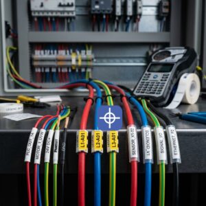
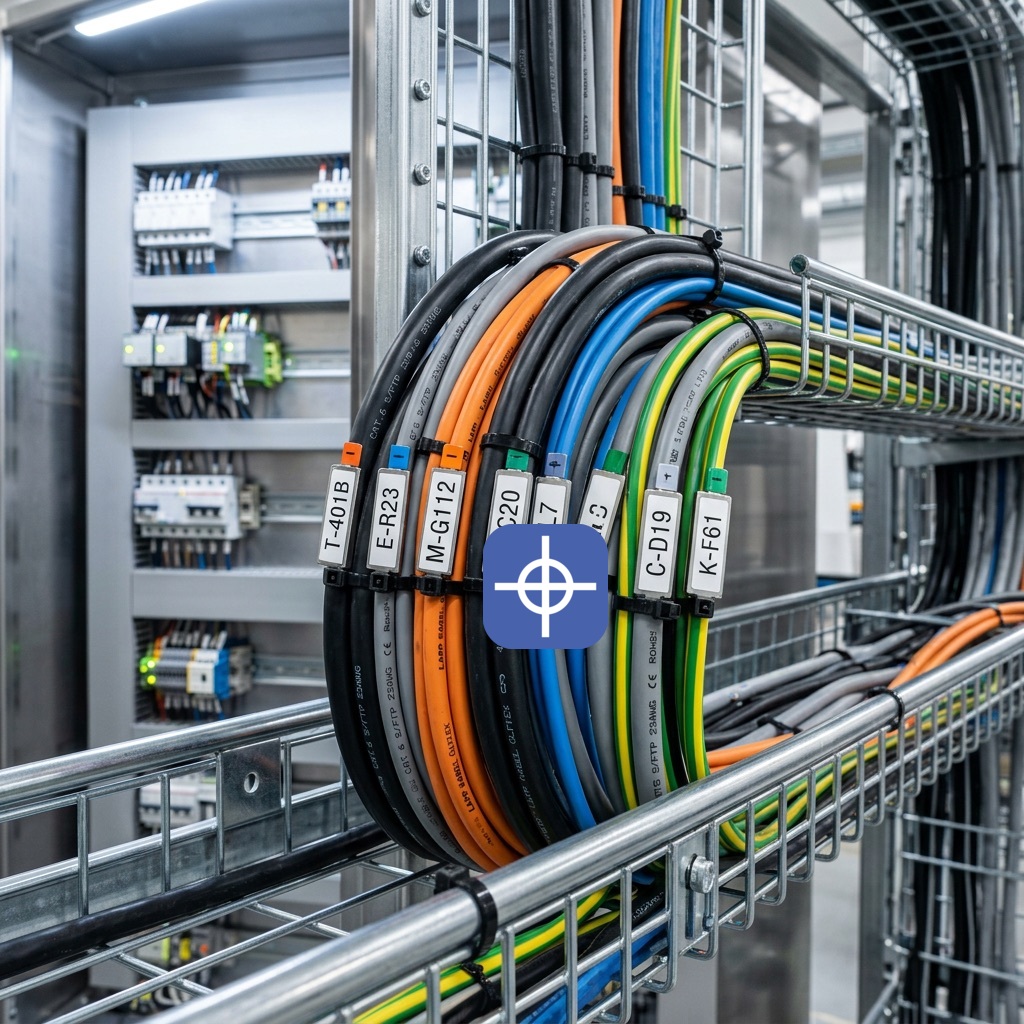
Prioritise legibility. Choose marker size and print quality so the identifier is readable at the viewing distance and angle inside the enclosure. Flag-style markers, which stand off from the conductor, are often the most readable in tight terminal areas.
Choose durability for the environment. Match the marking method to the conditions. Printed heat-shrink sleeves grip tightly and resist oil, vibration, and abrasion in demanding panels; self-laminating wrap-around labels add a clear overlaminate that protects the print; clip-on markers suit retrofits where conductors are already terminated. Durable marking is what keeps the number readable after years of service.
Keep marking and drawings in lockstep. The identifier on the wire must match the schematic, the terminal designation, and the as-built documentation exactly. Generate marking lists from the official project outputs so cross-referencing is reliable, and update the as-built drawings whenever a conductor changes. A number that no longer matches the drawing is worse than no number at all.
Verify before sign-off. Spot-check a sample of runs against the drawings, confirm both ends carry matching tags, and only then approve the panel as a whole.
How Radonix Wire Tags Integrate With These Systems
A numbering convention lives on paper until it is printed onto the conductor. Radonix wire tags are the physical layer that carries your scheme into the enclosure — the marker that maps a designed identifier to the installed wire.
Whatever convention you adopt, the tag can hold the elements that make a conductor traceable: the wire number itself, the source and destination (for example, from a terminal block position to a PLC I/O point), the cable and core number for multi-core cables, the signal or function name, the circuit class, and a drawing reference for larger projects. Because the tags are built to align with recognised identification and marking practices — including IEC 60445 conductor and terminal marking and durable-labelling expectations — the physical marking reinforces the compliance built into your numbering scheme rather than working against it.
For a deeper look at tag types, materials, and what to print on each conductor, see the Radonix guide to industrial wire tags and cable identification, which walks through clip-on, wrap-around, heat-shrink, and flag formats and how to choose between them. Selecting the right tag format for your environment is what turns a good numbering scheme on paper into a panel that stays readable for its full service life.
FAQ
What is the difference between a cable numbering system and a wire tag?
The numbering system is the logic — the convention that decides what identifier each conductor receives. The wire tag is the physical marker that carries that identifier on the wire. You design the system on the drawing; you apply it in the panel with tags. Both are needed, and both must agree.
Is IEC 60445 mandatory for cable numbering?
IEC 60445 sets general rules for identifying terminals and conductors, including colours and alphanumeric identifiers. Whether it is contractually required depends on your market, customer, and applicable regulations, but following it is good practice everywhere because it produces unambiguous, widely recognised marking. Many projects reference it alongside durable-labelling standards such as UL 969 for the marking material itself.
Sequential or functional numbering — which is better?
Neither is universally better. Sequential numbering wins on small, stable panels for its speed and simplicity. Functional numbering wins on large or frequently modified machines because the identifier carries circuit context and new wires slot in without renumbering. Match the method to the machine, not the other way round.
Should I number both ends of a cable?
Yes. Both terminations of every conductor should carry the same identifier. A run tagged at only one end cannot be traced once it enters a duct or loom, which defeats the purpose of numbering it at all.
How do I keep numbering consistent with my drawings?
Generate the wire numbers and the marking list from your electrical CAD project rather than assigning them by hand, tag from that single source, and update the as-built documentation whenever a conductor changes. When the drawing, the terminal designation, and the wire tag all originate from the same data, cross-referencing stays reliable.
Get Your Conductors Marked Right
A consistent cable numbering system is one of the cheapest investments you can make in a machine’s whole-life maintainability — and one of the most expensive omissions when it is skipped. Choose a convention that fits your machine, align it with IEC 60445 marking, overlay colour coding for instant recognition, and keep every tag in lockstep with the as-built drawings.
When you are ready to put that scheme onto the wire, Radonix wire tags and marking products give you durable, standards-aware identification that maps directly to your numbering scheme. Explore the Radonix wire tag and cable identification guide to choose the right format for your panel, or contact the Radonix team for guidance on marking your build end to end.
For industrial implementation, explore Radonix PC-based CNC controllers, control software and machine-specific HMI systems. Radonix PC-based CNC controller systems.