
Author: Nima Rad
Introduction
In industrial machinery, power cables, control cables, network cables, and pneumatic and hydraulic hoses have to move along with the machine’s moving axes. If these cables and hoses are left without a proper guiding system, they can end up stretched, twisted, worn, torn, or caught on the machine’s moving parts.
An energy chain, also called a cable carrier, is a mechanical, flexible component that guides and protects moving cables and hoses along a defined path. This part is also known in the market by several other names:
- Cable Carrier
- Drag Chain
- Cable Chain
- Cable guide chain
- Chain cable carrier
- Cable routing chain
Despite its name, an energy chain does not generate or store energy; instead, it manages the routing of power, data, air, oil, water, and other fluids through the moving parts of a machine. Manufacturers offer these components for linear, vertical, rotary, and 3D motion.
Internal Structure of an Energy Chain
An energy chain is usually built from a series of modular parts that connect to one another like the links of a chain.
1. Links or Side Plates
The links form the main body of the energy chain. Their articulated connection lets the chain bend in one direction while preventing it from over-bending or moving irregularly.
Each link has a mechanical stop that controls the chain’s bend radius.
(Technical diagram of internal components, crossbar and separator)
2. Crossbars
Crossbars connect the two sides of the chain and hold the cables inside it.
Depending on the model, these parts may be:
- Fixed;
- Openable from the inside;
- Openable from the outside;
- Openable from both sides;
- Designed as a fully closed cover.
Openable models make installing and replacing cables much easier. Some industrial series, for example, allow the crossbars to be opened from both the inner and outer radius.
3. Internal Separators
Separators divide the internal space of the chain into several sections.
Their job is to keep the following apart:
- Servo and spindle power cables;
- Encoder cables;
- Network and communication cables;
- Sensor cables;
- Pneumatic hoses;
- Hydraulic hoses;
- Water or cooling system tubing.
Proper separation prevents cables from overlapping, rubbing, tangling, and pressing against each other, which can extend the service life of the whole assembly.
4. Mounting Brackets
Both ends of the energy chain are attached to the machine using brackets:
- One side to the fixed part of the machine;
- The other side to the axis or moving part.
The bracket must be installed perfectly aligned, since any misalignment causes lateral twisting and uneven wear of the chain.
5. Cable Strain Relief
A strain relief system anchors the cables at the start and end of the travel path so that pulling force isn’t transferred directly to the socket, connector, terminal, or cable gland.
Improper cable strain relief is one of the main causes of failure in moving cables.
6. Guide Trough
On long travel paths, the energy chain usually moves inside a metal or polymer guide trough.
This channel:
- Prevents lateral deviation of the chain;
- Controls the back-and-forth path;
- Stabilizes sliding motion;
- Reduces friction and lateral impacts.
A guide trough is especially important for long travels, heavy loads, and gliding applications.
How an Energy Chain Works
One end of it is fixed while the other end connects to the moving axis. As the axis moves, the energy chain opens and closes in the shape of an arc or a U-shaped loop.
The stops built into the links prevent the energy chain from bending tighter than the specified radius, which means the cables inside also move with a controlled bend radius.
On short travel paths, the upper strand of the chain may move without touching the lower strand. This is called an unsupported application.
On longer travel paths, the upper strand of the energy chain slides on the lower strand or on a guiding surface. This is called a gliding application. The weight of the cables, travel length, speed, and acceleration determine how far the chain can travel without support. Each manufacturer’s load diagram should be used to check the free length and the allowable cable weight. Excessive sagging of the chain is a sign of an improper selection or overload.
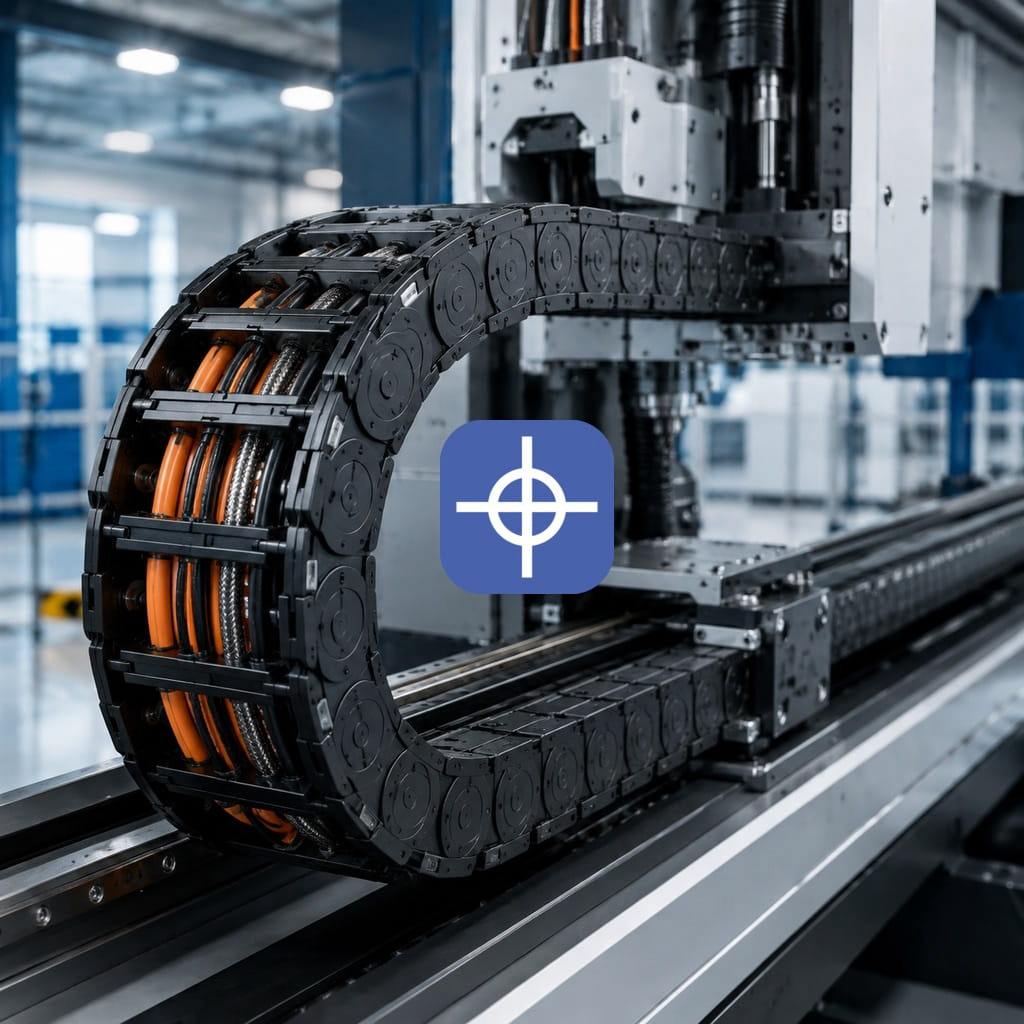
(A real-world view of an energy chain with cables and hoses)
Types of Energy Chains
1. Open Plastic Energy Chain
The most common type used in CNC machines and automation equipment.
This model is suitable for CNC wood-routing machines, printing, packaging, assembly, and general automation equipment.
2. Closed Energy Chain (Energy Tube)
In this model, the outer surface of the chain is covered with a lid.
For lathes, milling machines, grinders, laser and plasma equipment, and contaminated environments, a closed or semi-closed model is the better choice.
3. Metal Energy Chain
This model is made of steel, galvanized steel, or stainless steel.
Metal models are used in steel manufacturing, cranes, oil and gas, heavy machinery, and very harsh environments. TSUBAKI KABELSCHLEPP offers plastic, steel, stainless steel, and hybrid models for various applications.
4. Hybrid Energy Chain
This model usually has polymer links combined with aluminum crossbars.
Its main feature is that it can achieve a large inner width and higher load capacity without a major increase in weight.
5. 3D Energy Chain for Robotics
In industrial robots, cables don’t bend in just one plane; they may bend and twist at the same time.
For this kind of application, a 3D energy chain must be used. A standard linear model should not be used for the twisting motion of a robotic arm.
6. Rotary Energy Chain
This model is used for rotary tables, turntables, antennas, rotary assembly equipment, and machines with a C-axis.
In rotary systems, the chain is guided inside a circular channel or a dedicated guiding system.
7. Low-Noise, Low-Vibration Energy Chain
Low-noise models are used in measuring devices, laboratory equipment, printing equipment, high-speed lines, and any environment where noise matters.
8. Cleanroom Energy Chain
These models are designed for the pharmaceutical, electronics, semiconductor, and medical equipment industries, and must generate very few particles.
Key Parameters for Selecting an Energy Chain
Inner Height
The inner height must be greater than the diameter of the largest cable or hose, and the necessary free space must also be taken into account.
Inner Width
The inner width must be sufficient for all the cables, separators, and the space they need to move.
Completely filling the internal space of an energy chain is not correct. According to igus’s guidelines, electrical cables typically need at least around 10% free space, while hydraulic hoses need around 20% free space around them. The exact figure must be confirmed against the manufacturer’s instructions.
Bend Radius
The most important parameter in selecting an energy chain is the bending radius.
The chain’s bend radius must not be smaller than the minimum dynamic bend radius of any of the cables or hoses. The cable or hose with the largest minimum bend radius determines the required radius for the whole assembly.
When cable data isn’t available, a rough estimate of about 8 to 10 times the cable’s outer diameter is sometimes used, but the final figure should come from the cable’s datasheet. Choosing a larger radius generally reduces bending stress and extends cable life.
Travel Length
You need to determine how far the axis travels and where the energy chain’s fixed point sits along that path.
Placing the fixed point at the center of the stroke usually reduces the chain length needed, but the exact length should be determined with a calculation tool or the manufacturer’s table.
Weight of Cables and Hoses
The weight of the contents is usually calculated in kilograms per meter.
The heavier the internal load:
- The stronger the energy chain needs to be;
- The allowable free length decreases;
- Wear increases in gliding applications;
- A guide trough or roller system may be needed.
Speed and Acceleration
In high-speed machines, linear speed alone isn’t enough — acceleration, braking, and the number of motion cycles must also be checked.
An energy chain may be able to handle high speed but may not be suitable for extreme acceleration or a very high number of cycles.
Environmental Conditions
The following should be checked when making a selection:
- Ambient temperature;
- Presence of oil and chemicals;
- Dust;
- Humidity;
- UV radiation;
- Metal shavings;
- Sparks and molten splashes;
- Corrosive environments;
- ESD requirements;
- Cleanroom requirements.
Mounting Orientation
An energy chain can be installed in the following orientations:
- Horizontal;
- Vertical, hanging;
- Vertical, standing;
- On its side;
- Rotary;
Load capacity and the guiding method differ in each case.
Choosing the Right Cable for an Energy Chain
Simply placing an ordinary cable inside an energy chain doesn’t turn it into a moving cable.
The cable used must be designed for continuous flexing, or continuous motion. These cables typically have a special stranded core structure, insulation, jacket, and lay direction designed for repeated movement.
Using a fixed building cable or a standard industrial cable can cause the following problems:
- Broken internal conductors;
- Cracked jacket;
- Increased electrical resistance;
- Momentary dropouts;
- Encoder or network errors;
- Short circuits;
- Damage to the drive and controller.
The cable’s minimum bend radius must also be checked for dynamic use, not just the bend radius used for a fixed installation.
Correct Cable Layout Principles
Cables must not be pre-twisted The cable must be placed inside the energy chain without any initial twist. Pulling the cable off the side of a coil causes it to twist. The cable should be unwound straight off a reel instead.
Different cables should be separated It’s best to separate power, control, and hose lines from each other using separators.
In CNC machines, the spindle and servo motor cables should ideally be kept separate from:
- Encoder cables
- EtherCAT
- Ethernet
- Position sensor cables
- Low-voltage I/O cables
This separation is not a substitute for proper shielding and grounding, but it can reduce contact and mechanical pressure between different cables.
Cables must not be installed under tension The cable must sit on the chain’s neutral axis — meaning it shouldn’t press against the inner radius or be stretched against the outer radius.
After the cable strain relief is installed, the assembly should be checked at both the start and end of the stroke.
Cables must not be compressed against each other Cables need room to move slightly and freely. Irregular overlapping of cables causes friction, wear, and changes to their bend radius.
Hoses need more space Pneumatic and hydraulic hoses can change shape under pressure, temperature, and motion, so more free space should be allowed for them.
Steps to Install an Energy Chain
- Measure the travel length of the axis.
- Determine the location of the fixed and moving ends.
- List all the cables and hoses.
- Check their diameter, weight, and minimum dynamic bend radius.
- Select the appropriate inner height and width.
- Calculate the total content weight in kilograms per meter.
- Check the load capacity and free length of the chain against the manufacturer’s diagram.
- Install the brackets perfectly aligned.
- Place the cables inside the chain without twisting them.
- Separate power, control cables, and hoses using separators.
- Anchor the cables with a strain relief system.
- Move the axis by hand or at a very low speed through the full stroke.
- Check the condition of the cables at both ends of the path.
- Gradually increase the speed.
- Check for noise, impacts, cable tension, and lateral deviation.
Using Energy Chains in CNC Machines
In CNC machines, an energy chain is used on the X, Y, and Z axes, and sometimes on rotary axes as well.
The cables and hoses inside it may include:
- Servo motor power cable;
- Encoder cable;
- Spindle motor cable;
- Motor brake cable;
- Limit and home sensor cables;
- EtherCAT or Ethernet network cable;
- Controller I/O cables;
- Pneumatic hose;
- Lubrication hose;
- Coolant water tubing;
- Probe and measuring tool cable.
CNC Wood-Routing Machines
An open or semi-closed plastic model is usually suitable, as long as dust doesn’t dangerously build up in the joints.
Plasma Cutting Machines
The energy chain should be kept away from sparks, heat, slag, and sharp edges. In paths close to the cutting area, a closed, heat-resistant model or one with extra protection is the better choice.
Milling and Metal Lathe Machines
Because of metal shavings and coolant, using an Energy Tube or a model resistant to oil and shavings is recommended.
Laser Machines
Smooth motion, low vibration, and particle protection matter here. Some applications require a closed or low-particle model.
(Example of an energy chain installed on a CNC machine)
Advantages of Energy Chains
- Protects cables and hoses;
- Improves the machine’s wiring organization;
- Reduces motion-related failures;
- Controls the bend radius;
- Reduces maintenance time;
- Makes cable replacement easier;
- Increases safety;
- Suitable for various speeds and stroke lengths;
- Allows expansion or a change in the number of links;
- Can be used on linear, vertical, and rotary paths.
Disadvantages and Limitations
- Requires enough space for the bend radius;
- Adds weight to the moving axis;
- Creates friction in gliding applications;
- Requires precise load capacity calculations;
- Can generate noise at high speed;
- Requires cleaning in contaminated environments;
- Risk of link failure if the wrong model is chosen;
- Higher cost for high-quality industrial models;
- Requires the use of cables specifically rated for continuous motion.
Trusted Energy Chain Brands
igus One of the best-known manufacturers of polymer cable carriers and cables designed for continuous motion.
TSUBAKI KABELSCHLEPP A manufacturer of plastic, steel, stainless steel, and hybrid energy chain systems.
Murrplastik This company offers modular cable management and cable guide chain assemblies for machine building, robotics, cranes, and production lines.
Common Mistakes in Selection and Installation
- Choosing an energy chain based only on appearance or price;
- Using standard cable instead of continuous-flex cable;
- Choosing a bend radius smaller than the cable’s allowed value;
- Completely filling the internal space of the chain;
- Placing power cables and sensitive cables together without separation;
- Installing a cable with an initial twist;
- Over-stretching the cable;
- Anchoring cables incorrectly;
- Misaligned bracket installation;
- Using an open model in an environment with hot shavings;
- Ignoring the weight of the cables;
- Not calculating speed and acceleration;
- Skipping the guide trough on long travel paths;
- Using a linear model for 3D motion;
- Lubricating polymer joints without guidance;
- Ignoring unusual noise and lateral wear.
Quick Selection Guide for CNC Machines
For an initial selection, the following information should be known:
- Axis stroke;
- Maximum speed;
- Maximum acceleration;
- Number of daily cycles;
- Mounting orientation;
- Number of cables and hoses;
- Outer diameter of each cable;
- Weight per meter of cable;
- Minimum dynamic bend radius;
- Operating temperature;
- Presence of oil, shavings, dust, and sparks;
- Available space on the machine;
- Need for a cover or guide trough.
Once this information is gathered, the model should be matched against the manufacturer’s load diagram and technical tables.
Conclusion
The energy chain is one of the important, and sometimes overlooked, components in CNC machines and industrial automation systems. Its job isn’t just to keep cables tidy — it must control the bend radius, prevent twisting and stretching, and create a safe path for transferring power, control signals, data, and fluids.
To achieve a proper service life, the energy chain, cables, separators, strain relief system, and guide trough need to be designed as a single, unified assembly. Selecting one based only on width, height, or price isn’t enough — parameters such as bend radius, cable weight, travel length, speed, acceleration, and environmental conditions must all be considered together.
For industrial implementation, explore Radonix PC-based CNC controllers, control software and machine-specific HMI systems. Radonix PC-based CNC controller systems.