
Author: Nima Rad
Table of Contents
- What Is a Voltage Transformer?
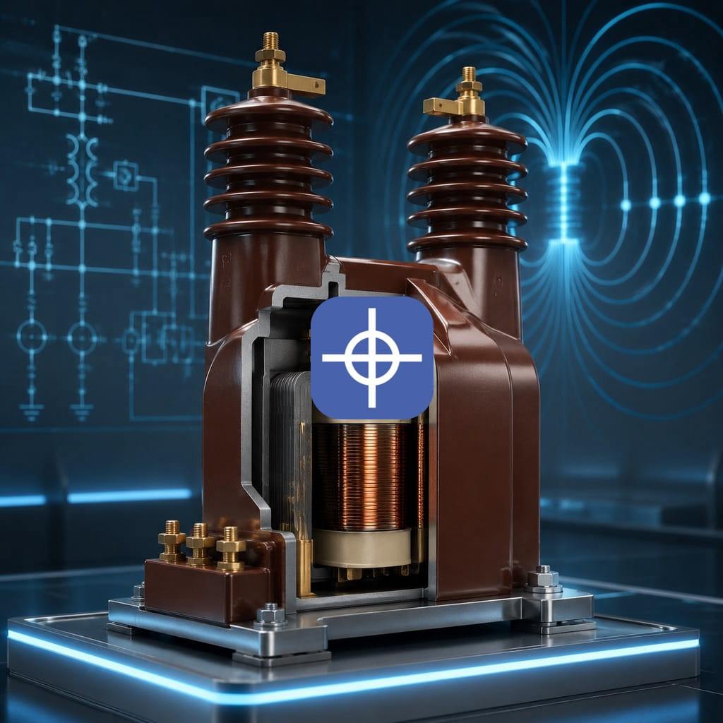
- Internal Structure of a Voltage Transformer
- Types of Voltage Transformers
- Types of Voltage Transformers by Core Shape
- What Unit Is Voltage Transformer Power Measured In?
- Using a Voltage Transformer in CNC Machines
- Advantages and Disadvantages of a Voltage Transformer
- Installation Tips and Common Transformer Mistakes
- Trusted Transformer Brands and Related Equipment
- Summary
Introduction
A voltage transformer is an electrical device that uses electromagnetic induction to raise or lower an AC voltage. For example, a suitable voltage transformer can convert 220V to 110V, 380V to 220V, or 220V to 24V. Voltage transformers are used in industrial equipment, electrical panels, CNC machines, laboratory equipment, imported home appliances, control systems, and many electrical circuits.
An important point is that standard transformers only work with alternating current (AC) and can’t be connected directly to DC power.
Internal Structure of a Voltage Transformer
A voltage transformer is usually made up of the following parts:
1. Primary Winding
The primary winding connects to the incoming power source. For example, in a 220-to-110V voltage transformer, the primary winding is connected to the 220V supply.
2. Secondary Winding
The converted voltage is drawn from the secondary winding. The number of turns in the secondary winding, relative to the primary, determines the output voltage.
3. Magnetic Core
The core provides the path for magnetic flux. It’s usually made of thin silicon-steel laminations to reduce losses from eddy currents.
High-frequency transformers may use ferrite cores instead.
4. Insulation
Insulating materials are used between the windings, the core, and the enclosure. Insulation quality has a direct effect on a voltage transformer’s safety, service life, and thermal tolerance.
5. Enclosure and Cooling System
Small transformers are usually cooled by natural air circulation, while larger transformers may have a fan, ventilation duct, or oil-cooling system.
How Does a Voltage Transformer Work?
Connecting an AC voltage to the primary winding creates a changing magnetic field in the core. This magnetic field passes through the secondary winding and induces a voltage in it.
The ratio of input to output voltage is approximately equal to the ratio of the number of winding turns:
V₁ / V₂ = N₁ / N₂
Where:
- V₁: primary winding voltage
- V₂: secondary winding voltage
- N₁: number of primary winding turns
- N₂: number of secondary winding turns
If the secondary has fewer turns than the primary, the voltage decreases. If the secondary has more turns, the voltage increases.
For example, if the secondary winding has half the turns of the primary, the output voltage will be roughly half the input voltage as well.
Voltage and Current Relationship in a Voltage Transformer
In an ideal transformer, input and output power are approximately equal:
V₁ × I₁ ≈ V₂ × I₂
So as voltage decreases, the available output current capacity increases, and as voltage increases, the available current decreases.
For example, a 1000VA voltage transformer with a 110V output can supply approximately the following current under ideal conditions:
I = 1000 ÷ 110 ≈ 9.1A
In practice, losses, ambient temperature, load type, and a safety margin also need to be taken into account.
Types of Voltage Transformers
1. Step-Down Transformer
This transformer reduces the input voltage.
Common examples:
- 380V to 220V
- 220V to 110V
- 220V to 48V
- 220V to 24V
- 220V to 12V
This type is used in control circuits, lighting systems, control equipment, and imported devices.
2. Step-Up Transformer
This transformer makes the output voltage higher than the input voltage.
Examples:
- 110V to 220V
- 220V to 380V
The main difference between step-up and step-down transformers is the number of turns in the primary and secondary windings and its effect on the output voltage.
3. Bidirectional Transformer
Some transformers can be used in either direction. For example, a voltage transformer rated 220-to-110V can, under specific conditions, also be used as a 110-to-220V transformer. However, before reverse use, the technical specifications, winding type, losses, fuse rating, and manufacturer’s recommendation should be checked.
4. Auto Transformer
In an auto transformer, the primary and secondary windings share part of a common path. This structure reduces the transformer’s weight, size, and price.
Advantages:
- Lower weight and volume
- More affordable
- Higher efficiency
- Lower voltage drop
Disadvantages:
- No full electrical isolation
- Possible transfer of a fault or dangerous voltage from input to output
- Lower safety in some applications
An auto transformer is very common for converting 220V to 110V in equipment that doesn’t require isolation.
5. Isolation Transformer
In an isolation transformer, the primary and secondary windings are electrically separated from each other, and energy is transferred only through the magnetic field. This transformer may have a 1:1 conversion ratio; for example: 220V Input → 220V Output.
The main purpose of this type isn’t to change the voltage, but to create electrical isolation and improve safety.
Applications:
- Medical equipment
- Electronics repair benches
- CNC machines
- Measuring equipment
- Reducing noise and ground loops
- Protecting the operator and sensitive circuits
6. Control Transformer
A control transformer is used to supply the command circuit voltage in industrial panels.
Common outputs:
- 24VAC
- 48VAC
- 110VAC
- 220VAC
These transformers are typically used to power contactors, relays, solenoid valves, and control circuits.
7. Three-Phase Transformer
A three-phase transformer is used for voltage conversion on three-phase networks.
Examples:
- 380V to 220V three-phase
- 400V to 230V three-phase
- 380V to 110V
- 220V three-phase to 380V three-phase
When selecting a three-phase transformer, the connection type (star or delta), presence or absence of a neutral, phase sequence, and line-to-line or line-to-neutral voltage must be defined.
Types of Voltage Transformers by Core Shape
EI Core Transformer
This type is built from core laminations shaped like the letters E and I.
Advantages:
- Affordable price
- Reasonably good repairability
- Wide variety
- Suitable for industrial applications
Disadvantages:
- Greater weight and volume
- More noise than toroidal models
- Higher leakage flux
Toroidal Transformer
This transformer’s core is ring-shaped, with the windings wound around it.
Advantages:
- High efficiency
- Lower noise
- Lower volume and weight
- Low leakage magnetic field
- Lower voltage drop
Disadvantages:
- Higher initial inrush current
- Greater sensitivity to DC components in the input power
- More difficult to repair and rewind
- Higher price
The main difference between EI and toroidal transformers lies in the core structure, the magnetic flux path, and the amount of field leakage.
How a Voltage Transformer Differs from an Electronic Converter
A voltage transformer and an electronic converter don’t work the same way.
Standard transformer:
- Based on a core and windings;
- Only works with AC power;
- Usually has a high weight;
- Has a simple structure and long service life;
- Keeps the output waveform roughly similar to the input.
Electronic converter:
- Uses semiconductor components and a switching circuit;
- Can be smaller and lighter;
- May produce AC or DC output;
- Is more sensitive to overload and fluctuations;
- May generate high-frequency noise.
For motors, transformers, pumps, CNC equipment, and industrial loads, a converter specifically designed for the intended load type should generally be used.
What Unit Is Voltage Transformer Power Measured In?
A voltage transformer’s capacity is usually specified in volt-amperes (VA) or kilovolt-amperes (kVA), not watts.
Apparent power formula for a single-phase system:
S = V × I
Approximate apparent power formula for a three-phase system:
S = √3 × V × I
For example, if a load operates at 220V and 4A:
220 × 4 = 880VA
So using a voltage transformer rated at exactly 880VA isn’t recommended; it’s better to allow for a safety margin and choose a model with a capacity of at least 1000 to 1200VA.
The Correct Way to Select a Voltage Transformer’s Capacity
To choose the right capacity for a voltage transformer, the following steps should be taken:
- Determine the input voltage The actual voltage at the installation site must be defined; for example:
- 220VAC single-phase
- 110VAC single-phase
- 380VAC three-phase
- 400VAC three-phase
- Determine the output voltage The device’s required voltage should be checked against its nameplate or manual.
- Check the current or power consumption The device’s nameplate usually lists one of the following:
- Power in W
- Capacity in VA
- Current in A
It’s best to base the capacity calculation on the device’s highest current draw.
- Identify the load type The load type has a major effect on the voltage transformer’s capacity selection.
Resistive load Such as heating elements and electric heaters. Starting current is usually low. Suggested capacity factor: about 1.2 times the load’s power.
Motor load Such as pumps, compressors, fans, and induction motors. Starting current may be several times the rated current. Suggested capacity factor: usually 2 to 3 times the rated power, depending on the starting method.
Capacitive or electronic load Such as switching power supplies, computers, servo drives, inverters, and CNC equipment. These loads can generate significant inrush current and harmonics. For these loads, the voltage transformer’s capacity should be chosen with a larger safety margin and based on the manufacturer’s recommendation.
- Allowing for a safety margin A voltage transformer shouldn’t run continuously at its maximum capacity. For general loads, continuous use at about 70–80% of rated capacity is more suitable.
Transformer Selection Example
Suppose an imported device has the following specifications:
- Device input voltage: 110V
- Current draw: 5A
- Available power: 220V
Apparent power of the device:
110 × 5 = 550VA
For a typical load, choosing a 700–1000VA voltage transformer is more suitable than a 550VA one.
If the device has a motor, compressor, or high starting current, a 1500VA transformer or even larger may be required.
Using a Voltage Transformer in CNC Machines
In CNC machines, a voltage transformer may be used for the following purposes:
- Supplying the command circuit voltage
- Powering contactors and relays
- Supplying power to solenoid valves
- Powering the panel’s lighting system
- Isolating the control circuit from grid power
- Supplying power to 110V imported equipment
- Reducing noise and improving safety
- Powering measurement and control equipment
In CNC panels, it’s best to keep the control transformer at a suitable distance from power equipment such as inverters, servo drives, and motor cables, to reduce induced noise. To power CNC controllers and electronic equipment, a regulated AC/DC power supply is typically used after the voltage transformer. A voltage transformer alone isn’t a substitute for an industrial 24VDC power supply.
Advantages of a Voltage Transformer
- Simple, reliable structure
- Relatively long service life
- Ability to raise or lower voltage
- Ability to provide electrical isolation
- Good tolerance in industrial environments
- Easy maintenance
- Can be built with custom voltages
- Reasonable resistance to short-term overloads
- No need for complex control circuits in standard models
Disadvantages of a Voltage Transformer
- High weight and volume, especially at higher power ratings
- Generates heat during operation
- Produces hum noise or vibration
- Copper and core losses
- No precise output voltage regulation under changing load
- Can’t change frequency
- Inrush current at the moment of connection
- Risk of electric shock in non-isolated models
- Voltage drop if the wrong capacity is selected
Voltage Drop and Transformer Regulation
A voltage transformer’s no-load output voltage is usually a bit higher than its rated value. Once a load is connected, the output voltage drops.
This voltage change is described by a characteristic called Voltage Regulation.
In higher-quality transformers, the full-load voltage drop is smaller. For sensitive loads, the Regulation value, instantaneous current, and the device’s minimum acceptable voltage should be checked.
Inrush Current
At the moment a voltage transformer is connected to power, a very large current may briefly be drawn from the grid. This current depends on factors such as the connection point in the AC cycle, residual core flux, core type, and voltage transformer capacity.
Toroidal transformers usually have higher inrush current than EI transformers.
The following equipment can be used to control inrush current:
- Slow-blow fuse
- A miniature circuit breaker with a suitable trip curve
- Soft-start circuit
- NTC resistor
- Bypass contactor
- Inrush current control relay
Voltage Transformer Installation Tips
- Install the voltage transformer on a solid, non-flammable surface;
- Leave enough space around it for air circulation;
- Don’t cross-connect the input and output;
- Insulate any unused terminals;
- Choose input and output wires sized for the current;
- Ground the metal enclosure;
- Don’t install the voltage transformer near a heat source;
- Don’t over-tighten the mounting screws, especially on a toroidal transformer;
- On a toroidal transformer, the center bolt must not create a short-circuited metal loop around the core;
- Measure the output voltage with a multimeter before connecting the load;
- For three-phase transformers, check the phase sequence and star or delta connection;
- In industrial panels, keep the transformer’s cables away from inverter and servo drive output cables.
Common Selection and Usage Mistakes
Choosing a voltage transformer based only on wattage Current, VA rating, power factor, and load type should also be checked.
Choosing a capacity that exactly matches the device’s consumption This causes overheating, voltage drop, and a shorter voltage transformer life.
Ignoring motor starting current Motors and compressors can draw several times their rated current when starting.
Using an auto transformer instead of an isolation transformer An auto transformer doesn’t provide safety isolation and isn’t suitable for some sensitive equipment or repair benches.
Connecting an AC transformer to DC power Connecting a standard transformer’s winding to DC can cause very high current, overheating, and burnt windings.
Ignoring frequency A 60Hz transformer may not perform properly on a 50Hz grid.
Connecting a load larger than the capacity A prolonged overload causes voltage drop, insulation damage, and a burnt-out transformer.
Using it without a fuse A short circuit in the wiring or load can cause severe damage and a fire risk.
Poor ventilation Placing the voltage transformer in a closed enclosure with no air circulation raises the winding temperature.
Trusted Transformer Brands and Related Equipment
In the global and industrial market, various brands are active in control, isolation, and voltage-conversion transformers. Well-known brands include:
- Schneider Electric
- Siemens
- ABB
- Legrand
- Phoenix Contact
- Eaton
- Hammond Manufacturing
- Block Transformatoren
- Murrelektronik
- Mean Well (for certain transformer and power supply models)
- Acme Electric
Beyond the brand, the actual technical specifications, copper wire quality, core type, insulation class, temperature rise, manufacturing standard, and after-sales service also matter a great deal. For custom locally-made transformers, wire cross-section, insulation quality, actual core weight, continuous power rating, and operating temperature should also be checked.
Important Standards and Specifications
When selecting an industrial voltage transformer, it’s best to pay attention to the following specifications:
- Rated power in VA or kVA
- Primary and secondary voltage
- Frequency (50/60Hz)
- Insulation class
- Allowable temperature rise
- IP protection rating
- Efficiency
- Voltage drop percentage
- Short-circuit withstand
- Cooling type
- IEC or UL standards
- Mounting type: DIN rail, panel-base, or wall
- Presence of an electrostatic shield
- Presence of a thermostat or thermal fuse
How to Evaluate a Voltage Transformer’s Quality
Signs of a high-quality transformer include:
- Weight proportional to its stated power
- Use of standard copper wire
- Acceptable operating temperature
- Low, consistent noise
- Low voltage drop at full load
- Proper insulation
- Complete technical specifications and nameplate
- Safe, high-quality terminals
- Thermal protection in industrial models
- No smell of burnt insulation at rated load
- A test report or valid standard certification
An unusually low weight in a 50Hz transformer can be a sign of an undersized core, wire with too small a cross-section, or actual power lower than the value stated.
Conclusion
A voltage transformer is one of the key components in power systems and industrial automation, used to raise or lower AC voltage and, in some models, to provide electrical isolation.
Choosing the right voltage transformer shouldn’t come down to input and output voltage alone; apparent power, starting current, load type, frequency, environmental conditions, isolation requirements, protection system, and cooling method must all be considered as well.
Choosing a voltage transformer with insufficient capacity can cause voltage drop, overheating, poor equipment performance, and a shorter device life. On the other hand, selecting the right capacity, installing it correctly, grounding it properly, and using fuses and thermal protection ensures the system runs reliably over the long term.
For industrial implementation, explore Radonix PC-based CNC controllers, control software and machine-specific HMI systems. Radonix PC-based CNC controller systems.