
Author: Nima Rad
Surface Scanning Capability
Table of Contents
- Introduction to Surface Scanning Capability
- Equipment and Different Surface Scanning Methods
- Surface Scanning Steps and Creating a Height Map
- Processing Surface Scanning Data and Interpolation Methods
- Adapting the Toolpath to the Part’s Real Surface (Toolpath Compensation)
- Offline and Real-Time Toolpath Compensation Methods
- 3D Scanning and Adaptive Machining Technology
- Surface Scanning Applications Across CNC Machining Processes
- Advantages, Limitations, and Trusted Surface Scanning Equipment Brands
- Summary
Introduction
Surface scanning is one of the advanced capabilities in modern CNC machines that lets the controller adapt the tool’s path to the part’s real surface. In many CNC machining processes, it’s assumed that the part’s actual surface sits exactly where it’s defined in the CAM software or CNC program. But in real conditions, factors such as part warping, surface unevenness, changes in material thickness, clamping errors, sheet deformation, table error, or casting-part tolerances can create a gap between the part’s actual surface and the surface defined in the program.
One advanced way to address this problem is using Surface Scanning or Surface Mapping capability. In this method, a measurement system first performs surface scanning on the part’s actual surface, and the tool’s path is then corrected based on that real surface data.
This process is usually referred to by terms such as Surface Scanning, Surface Mapping, Height Map Compensation, Surface Compensation, Adaptive Toolpath, and Adaptive Machining.
In the simplest case, only the Z-axis position is corrected, but on more advanced 3D and 5-axis systems, the tool’s angle and orientation can also change to match the real surface, in addition to its position.
What Is Surface Scanning?
Surface Scanning is a process in which a number of points on the part’s actual surface are measured. Each point usually includes X, Y, and Z coordinates. By measuring a large number of these points, the controller or software can estimate the surface’s real shape.
For example, if a part’s surface is theoretically supposed to sit at Z = 0, an actual scan might show the following values:
- X = 0, Y = 0 → Z = +0.15 mm
- X = 200, Y = 0 → Z = -0.20 mm
- X = 200, Y = 300 → Z = +0.40 mm
This information shows that the part’s surface isn’t perfectly flat. The controller can use this same information to correct the tool’s path.
Height Map
One of the most common ways to represent a scanned surface is a Height Map. A Height Map is essentially a two-dimensional grid of X and Y coordinates, where the Z height is stored for each point.
Using this information, the controller can calculate an approximate shape of the part’s real surface. The closer together the surface scanning points are, the more accurate the surface map becomes, but scanning time and data volume increase as a result.
Equipment Used for Surface Scanning
Surface scanning can be done using different methods.
Touch Probe One of the most common methods is using a Touch Probe. In this method, a measuring probe is mounted on the spindle or an axis of the machine. The controller moves the probe toward different points on the surface, and at the moment the stylus touches the part, the axis position is recorded. This coordinate is then stored as the surface height.
Analog Scanning Probe Unlike a Touch Trigger Probe, which only detects the moment of contact, an Analog Scanning Probe continuously measures changes in the stylus’s position. This method is used for faster, more precise surface scanning of 3D surfaces.
Laser Sensor This method measures without contact. A laser sensor measures the distance between the sensor and the part’s surface. This method is widely used for soft, sensitive, delicate parts, or surfaces where mechanical contact isn’t suitable.
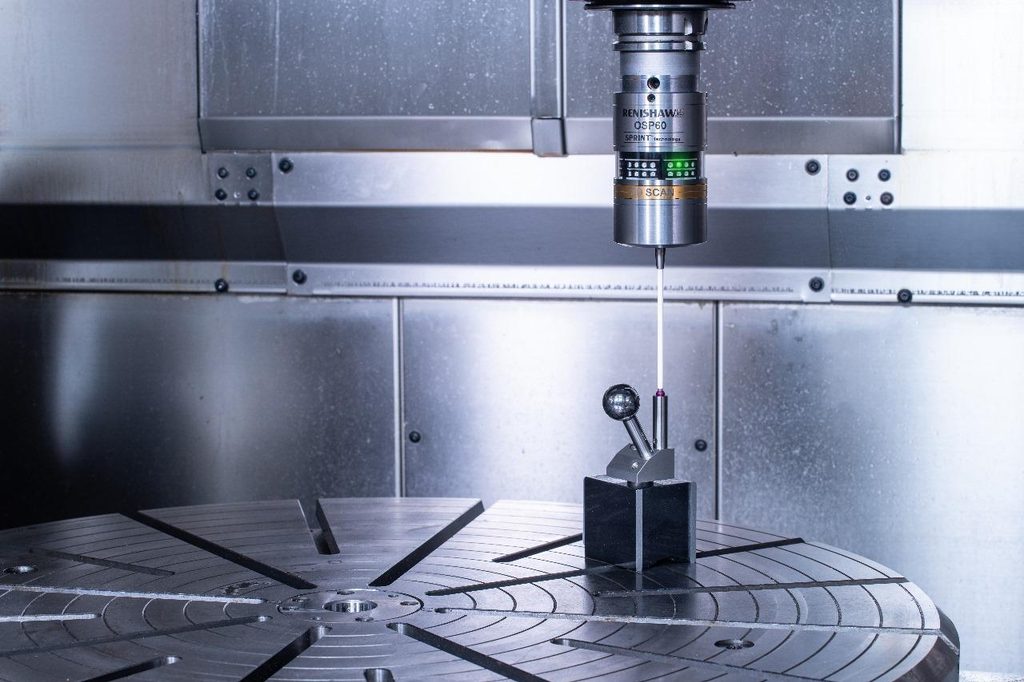
Industrial probe used for surface scanning on a CNC machine
An example of an industrial probe used for measuring and surface scanning parts on a CNC machine
Other Methods More advanced systems can also use:
- Laser Line Scanner
- Structured Light
- Confocal Sensor
- Optical Distance Sensor
- 3D Scanner
Surface Scanning Process Steps
The typical surface scanning process on a CNC machine includes the following steps.
First, the area for surface scanning is defined; for example, X Start = 0, X End = 500mm, Y Start = 0, and Y End = 300mm.
Then the distance between surface scanning points, or Scan Step, is set; for example, X Step = 20mm and Y Step = 20mm.
Based on these values, the controller creates a grid of points. The probe then moves to each point on the grid in sequence and measures the surface height. Once scanning is finished, all measured points are stored and a Height Map is built.
Interpolation Between Surface Scanning Points
The tool doesn’t necessarily pass exactly through the points recorded during surface scanning while machining.
For example, suppose X = 100 → Z = 0.20mm and X = 120 → Z = 0.40mm, but the tool passes through X = 110 during machining. In this case, the controller needs to calculate the approximate surface height at that position. This process is called interpolation.
Common methods include:
- Nearest Point
- Linear Interpolation
- Bilinear Interpolation
- Bicubic Interpolation
- Spline Interpolation
On many Height Map systems, Bilinear Interpolation is a suitable choice, since it computes quickly and produces smooth, predictable behavior.
Adapting the Toolpath to the Real Surface
Suppose the CAM program generates the following command: X100 Y100 Z-1, meaning the tool needs to travel one millimeter into the part’s surface.
If the Surface Map shows that the real surface at this point sits at Z = +0.30mm, the controller corrects the tool’s path. In the simple case:
Z Corrected = Z Programmed + Z Surface
So:
Z Corrected = -1 + 0.30 = -0.70mm
This way, the actual machining depth relative to the part’s surface stays at one millimeter. This is the core concept behind Surface Compensation.
Correcting the Path During Motion
Height correction shouldn’t only happen at the start and end of a move.
Suppose the program has the command G1 X500 Y0 Z-1. If the surface height changes along this path, the Z axis needs to change simultaneously with the X motion; for example:
- X0 → Z-1.00
- X100 → Z-0.90
- X200 → Z-0.75
- X300 → Z-1.10
- X400 → Z-1.20
- X500 → Z-0.95
So the Z axis is constantly making a compensating move on top of the original toolpath.
Offline and Online Methods for Toolpath Compensation
There are usually two main methods for implementing Surface Compensation.
Offline Compensation In this method, surface scanning is done first. The software then processes the G-code file based on the Height Map and generates a new, corrected G-code. The main advantage of this method is that it’s simpler to implement on the controller. But if the surface map changes, the G-code needs to be regenerated.
Online, or Real-Time, Compensation In this method, the original G-code stays unchanged. As the path runs, the controller checks the current X and Y position and calculates the Z Correction value directly from the Surface Map.
What Is a Point Cloud?
On advanced scans, data may not be stored as a regular grid. In this case, a large number of 3D points on the surface are measured, and this collection is called a Point Cloud. Each point includes X, Y, and Z.
A Point Cloud can later be converted into a Mesh, Surface, NURBS Surface, or STL Model. This method is mostly used in reverse engineering and adaptive machining of complex surfaces.
The Difference Between Surface Mapping and Reverse Engineering
These two concepts are closely related but have different goals.
In Surface Mapping, the main goal is to determine the surface error to correct the tool’s path; conceptually: Compensation Map = Actual Surface – Reference Surface.
In Reverse Engineering, the goal is to fully reconstruct the part’s geometry. So reverse engineering usually needs a denser point cloud and more complex geometric processing.
Surface Scanning Applications Across CNC Machining Processes
Use in CNC Engraving
One of the most important applications of Surface Compensation is in engraving. Suppose text needs to be engraved at a depth of 0.1mm on a metal plate. If the part’s surface has just 0.2mm of warp, the tool might not touch the surface at all in one area and cut too deep in another. Using surface scanning, the Z axis constantly adjusts, and the engraving depth relative to the actual surface stays roughly constant.
Use in PCB Milling
This capability matters a great deal in PCB milling. The cutting depth of copper traces is very small, and even a height difference of a few hundredths of a millimeter can change the cut quality. For this reason, the PCB’s surface is scanned first and a Height Map is generated; the tool’s path is then corrected based on this map.
Use on Warped Sheets
Large sheets are usually not perfectly flat. In operations such as metal engraving, wood engraving, composite machining, plasma cutting, and laser processing, the surface height may change across the table. Surface Mapping can measure and compensate for these variations.
Use in Mold Making and 3D Surfaces
In mold making, the situation is more complex, since the reference surface is itself 3D. In this case, the difference between the Nominal Surface and the Measured Surface needs to be calculated. Under these conditions, a simple Z-axis correction isn’t always enough, and the toolpath may need to be corrected in a direction perpendicular to the surface.
Surface Normal Compensation
On complex 3D surfaces, correcting along Z alone doesn’t always give a correct result. Suppose the tool moves across a steeply sloped surface. If the surface error is 0.2mm, a 0.2mm Z-axis move isn’t necessarily equal to a 0.2mm correction relative to the surface. A more accurate method is applying the correction along the Surface Normal direction. In this method, the surface’s normal vector is calculated, and the correction is applied in that same direction. This matters a great deal in 3D and 5-axis machining.
3D Scanning and Adaptive Machining Technology
Adaptive Machining is one of the more advanced stages of Surface Compensation. In this method, each part’s actual geometry is measured first, and the toolpath is then adjusted to match that specific part. This method is very well suited to parts whose initial shape isn’t fully predictable.
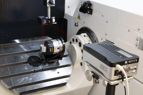
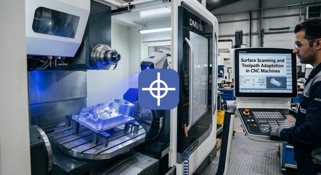
Example of scanning a part’s surface on a CNC machine to extract its real geometry
An example of scanning a part’s surface on a CNC machine to extract its real geometry and correct the toolpath
Use in Deburring
Suppose a cast part has an edge whose position varies slightly from part to part. If the deburring path runs directly from the CAD model, the tool might not travel exactly along the real edge. In adaptive machining, surface scanning is done on the part first; the edge’s real position is then detected, and the toolpath is corrected to match the actual geometry.
Choosing the Number of Surface Scanning Points
Choosing the Scan Resolution matters a great deal.
If the spacing between points is large, surface scanning time and data volume decrease, but small surface variations may go undetected.
If the spacing between points is small, the surface model’s accuracy increases, but surface scanning time and computation volume also increase.
So the Scan Step should be chosen based on the part’s dimensions, the amount of unevenness, the required accuracy, and the type of operation.
Filtering Surface Scanning Data
Sensor data may contain noise or unusual points; for example:
- 0.100
- 0.102
- 0.098
- 0.450
- 0.101
The value 0.450 is likely an outlier. So a professional surface scanning system needs capabilities such as noise filtering, outlier detection, and smoothing. Otherwise, the corrected path could cause sudden Z-axis movements.
Limiting the Compensation Value
One of the most important safety features is setting a Maximum Compensation; for example, Maximum Positive Compensation = +2mm and Maximum Negative Compensation = -2mm.
If the measured difference exceeds this value, it’s best for the system to stop the operation. This condition can indicate a clamping mistake, an obstruction or foreign object, a faulty probe, an incorrect work offset selection, or a part placed incorrectly on the table.
Safe Z During the Surface Scanning Process
During surface scanning, a safe height needs to be defined for the probe’s movement. Important parameters can include Safe Z, Probe Start Height, Maximum Probe Depth, and Probe Feedrate.
The probe first moves to the safe area at a suitable speed, then approaches the surface at a controlled feedrate. Choosing these parameters incorrectly can cause the probe to collide with the part.
Probe Calibration
Probe calibration needs to be performed to achieve suitable accuracy. Important items include Stylus Length, Stylus Radius, Probe Trigger Offset, Probe Center Offset, and Probe Runout. On precise systems, even changing the stylus can require recalibration.
Factors Affecting Surface Scanning Accuracy
The system’s final accuracy doesn’t depend on probe accuracy alone. Other factors also matter:
- Servo following error
- Ball screw error
- Linear scale error
- Spindle runout
- Calibration error
- Thermal expansion
- Machine vibration
- Probing speed
- The part’s surface quality
Comparing Touch Probe and Laser Scanner
A Touch Probe is usually a suitable choice for precisely measuring specific points and hard surfaces. Its advantages include high accuracy, good stability, and low sensitivity to surface color. But its point-by-point surface scanning speed is usually lower.
A Laser Scanner is much faster and can capture a large number of points in a short time. But it may be sensitive to surface color, light reflection, transparency, surface angle, or surface contamination.
Continuous Scanning Probe
In a Continuous Scanning system, the stylus stays in constant contact with the surface. The machine moves at the same time, and surface data is measured at a high rate. Compared to point probing, this method collects far more data in less time and is very well suited to freeform surfaces.
Technical Structure of a Surface Scanning System
A complete Surface Compensation system can be made up of the following parts: Sensor Interface, Probe Manager, Scan Path Generator, Data Acquisition, Height Map Manager, Point Cloud Manager, Filtering, Interpolation Engine, Compensation Engine, Motion Planner, and Visualization.
Data received from the sensor is processed and ultimately converted into a surface model.
Real-Time Architecture
On an advanced CNC controller, processing Surface Compensation shouldn’t disrupt the motion cycle. So it’s best for the Height Map to be built before machining starts. During execution, only the required correction value should be calculated using a fast interpolation.
For example, in a system with a cycle time of 1ms: the command position is calculated, the X and Y position is determined, the Height Map is checked, the Z compensation is calculated, the correction is added to the command position, and finally the command is sent to the axis. These calculations need to be fast and deterministic.
Z-Axis Speed and Acceleration Limits
Surface Compensation can create large changes on the Z axis. If the surface changes height sharply over a short distance, the Z axis needs to move at high speed and acceleration. So the following limits need to be checked: Z Velocity, Z Acceleration, and Z Jerk. If the axis can’t keep up with the path, the feedrate needs to be reduced.
Using Look Ahead
Look Ahead can improve Surface Compensation quality. The controller checks the upcoming path and already knows what height change lies ahead. As a result, it can adjust the motion speed so the Z axis doesn’t exceed its speed and acceleration limits.
Surface Compensation on 5-Axis CNC
On a 5-axis machine, things get more complex. On these machines, besides the tool tip’s position, the tool axis’s direction matters too. If the real surface has changed relative to the CAD model, both the tool position and tool orientation may need to be corrected. This capability matters a great deal in adaptive machining of parts such as blades and impellers.
Advantages, Limitations, and Trusted Surface Scanning Equipment Brands
Advantages of Surface Scanning
The most important advantages of surface scanning include:
- Maintaining a constant machining depth relative to the real surface
- Reducing the effect of part warping
- Reducing sensitivity to setup error
- Improving engraving quality
- Improving machining accuracy
- Reducing the need for very precise fixtures
- Reducing scrap
- Reducing rework
- The ability to machine parts with variable geometry
- Increasing the CNC machine’s flexibility
Limitations of Surface Scanning
- Surface scanning isn’t a substitute for the machine’s mechanical accuracy. If the machine has backlash, vibration, servo error, or mechanical issues, surface scanning can’t compensate for every error.
- Very dense surface scanning can take a lot of time.
- On optical systems, the part’s surface characteristics can also affect the measurement result.
Leading Brands in CNC Measurement Systems
Well-known brands in touch probes and CNC measurement systems include:
- Renishaw
- HEIDENHAIN
- Blum-Novotest
The Difference Between Tool Length Compensation and Surface Compensation
Tool Length Compensation and Surface Compensation are two different capabilities. Tool Length Compensation, such as G43, is used to compensate for tool length. Surface Compensation is used to compensate for changes in the part’s surface height. Both capabilities can be active at the same time.
Conceptually: Programmed Z + Tool Offset + Work Offset + Surface Compensation. Exactly how these offsets are applied depends on the controller’s architecture.
The Difference Between Surface Compensation and THC
Surface Compensation is conceptually very similar to Torch Height Control on a plasma machine. In both cases, the Z axis’s position is corrected relative to the part’s surface. But the information source is different.
In Surface Mapping, the surface is usually scanned before machining starts. In THC, the height is adjusted in real time during the operation, usually based on arc voltage. On advanced systems, a combination of a Surface Map and a feedback sensor can even be used.
Summary
Surface scanning and toolpath adaptation is one of the most practical technologies in modern CNC controllers. In this technology, the part’s real surface is first scanned using a Touch Probe, Scanning Probe, Laser Sensor, or another measurement system.
The resulting data can be stored as a Mesh, Point Cloud, Height Map, or 3D model. The controller then calculates the difference between the real surface and the reference surface and corrects the tool’s path. In simple applications, correction is applied only to the Z axis, but on more advanced systems, XYZ and even tool orientation can be corrected too.
Surface scanning is widely used in engraving, PCB milling, deburring, chamfering, mold making, machining cast parts, reverse engineering, adaptive machining, and 5-axis machining.
From a controller-design perspective, a suitable structure can look like this:
Nominal Toolpath ← Surface Map ← Interpolation ← Surface Compensation ← Motion Planner ← Servo Command
Such an architecture, besides Surface Compensation, also makes it possible to develop more advanced capabilities such as adaptive machining, auto-leveling, 3D surface following, and copy machining.
For industrial implementation, explore Radonix PC-based CNC controllers, control software and machine-specific HMI systems. Radonix PC-based CNC controller systems.