

Author: Nima Rad
Table of Contents
- What Is a Relay?
- Internal Structure of a Relay and Why It’s Used
- Types of Relays
- Key Specifications for Selecting a Relay
- Using a Relay in CNC Machines
- Important Installation and Usage Tips
- Trusted Relay Brands
- Common Mistakes in Using Relays
- General Advantages and Disadvantages of Relays
- Summary
Introduction
A relay is an electrical or electronic switch that, upon receiving a control command, opens or closes the current path in another circuit. Relays make it possible to control high-voltage, high-current loads using a weak signal.
For example, the output of a CNC controller, PLC, microcontroller, or control card may not have enough power to directly drive a solenoid valve, contactor, pump, motor, or lamp. In this situation, the controller’s output first energizes the relay, and its contacts open or close the load circuit.
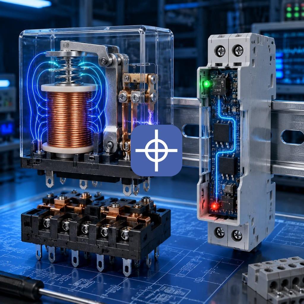
Internal Structure of an Electromechanical Relay
This type is usually made up of the following parts:
1. Coil (Bobbin)
The coil generates a magnetic field when voltage is applied. The coil voltage can be one of the following values:
- 5V DC
- 12V DC
- 24V DC
- 24V AC
- 110V AC
- 220V AC
In industrial electrical panels and CNC machines, models with a 24V DC coil are very common.
2. Iron Core
The magnetic field created by the coil magnetizes the iron core, causing it to attract the moving part.
3. Armature (Moving Lever)
The armature moves under magnetic force and changes the state of the contacts.
4. Return Spring
Once the coil is de-energized, the spring returns the armature and contacts to their original position.
5. Contacts
The contacts are responsible for opening or closing the load circuit. Their three main terminals are:
- COM or Common: the shared terminal
- NO or Normally Open: contact normally open
- NC or Normally Closed: contact normally closed
6. Housing and Base
The housing protects the internal components. In industrial examples, the unit is typically mounted on a rail-mount socket to make replacement and wiring easier.
How a Relay Works
When a suitable voltage is applied to the coil, the following steps occur:
- Current flows through the coil.
- A magnetic field is created.
- The iron core attracts the moving armature.
- The NO contact closes.
- The NC contact opens.
- The load circuit changes state.
Once the coil voltage is removed, the magnetic field collapses, and the spring returns the contacts to their original position.
Understanding NO and NC Contacts
NO Contact
A Normally Open contact is open under normal conditions and doesn’t conduct current. When the coil is energized, this contact closes.
Common applications:
- Turning on a lamp
- Activating a solenoid valve
- Starting a contactor
- Turning on a pump
- Activating a cooling system
NC Contact
A Normally Closed contact is closed under normal conditions and conducts current. When the coil is energized, this path opens.
Common applications:
- Stop and safety circuits
- Fault signaling
- Disconnecting equipment under specific conditions
- Electrical interlocking
- Monitoring the health of a control circuit
Why Relays Are Used
These components are used in industrial circuits for the following reasons:
Electrical isolation In the electromechanical type, the control circuit and the power circuit are electrically separated from each other. This prevents dangerous voltages from being transferred directly to the controller.
Increasing output power A PLC or controller’s output may only provide a few dozen or a few hundred milliamps of current, but a relay can control loads with much higher current.
Signal type conversion Using one, a 24V DC command can be used to switch a 220V AC circuit on and off.
Increasing the number of contacts Some models have several independent contacts, letting a single command control multiple circuits at once.
Protecting the controller’s output An interposing relay can protect a PLC output, CNC controller, or electronic board against high current and load-induced noise.
Building logic circuits Using NO and NC contacts, interlock, latching, priority, delay, and safety circuits can be built.
Types of Relays
1. Electromechanical Relay
This type has a coil and mechanical contacts.
Advantages:
- Complete isolation between the control and power circuits
- Can control both AC and DC loads
- Affordable price
- Easy to check operating status
- Good tolerance for momentary overloads
Disadvantages:
- Mechanical wear on the contacts
- Produces noise when switching
- Limited switching speed
- Creates sparking at the contacts
- Limited life in high-cycle applications
2. Solid State Relay (SSR)
A Solid State Relay has no mechanical contacts; switching is done by semiconductor components.
Advantages:
- Silent operation
- High switching speed
- Long service life
- Suitable for frequent switching
- No mechanical sparking
Disadvantages:
- Generates heat
- May require a heat sink
- Leakage current in the off state
- Greater sensitivity to overcurrent
- Higher price than a standard model
- Requires a separate model for AC or DC loads
The SSR type is typically used to control heaters, heating elements, thermal systems, packaging equipment, and applications with a high switching count.
3. Timer Relay
This type performs its switching operation with a delay after receiving a command.
Common types include:
- ON Delay: turns on after a delay
- OFF Delay: turns off after a delay
- Interval: activates for a set period
- Cyclic: switches on and off periodically
- Star-Delta Timer: used for star-delta motor starting
4. Thermal (Bimetal) Relay
This type protects a motor against prolonged overload. It’s usually installed alongside a contactor in the motor circuit. The thermal type isn’t suitable for short-circuit protection and should be used together with a fuse or a suitable protective breaker.
5. Phase Control Relay
This type monitors the condition of a three-phase network and issues a trip command under abnormal conditions.
Conditions it can detect include:
- Loss of one phase
- Reversed phase sequence
- Overvoltage
- Undervoltage
- Phase asymmetry
- Severe grid fluctuation
6. Glass (General Industrial) Relay
These models typically have a transparent housing, multiple contacts, and a rail-mount socket. Being able to see the internal state and swap them quickly are among their advantages.
Common configurations:
- Single contact
- Double contact
- Triple contact
- Quadruple contact
7. Interface Relay
This type sits between a PLC or controller output and the load. Interface models are usually slim, rail-mounted, and have an LED indicator.
Important applications:
- Protecting a PLC output
- Controlling solenoid valves
- Starting a contactor
- Increasing the number of outputs
- Converting a transistor output to a dry contact
8. Protective Relay
This type is used in power networks, substations, generators, and power equipment.
Some common types include:
- Overcurrent relay
- Ground fault relay
- Differential relay
- Voltage relay
- Frequency relay
- Reverse power relay
- Motor protection relay
Relay vs. Contactor
Both of these components are used to open and close circuits, but they differ in capacity and application.
For direct control of high-power motors, large heaters, and three-phase loads, a contactor is more suitable. A relay can be used to control the contactor’s coil command.
Key Specifications for Selecting a Relay
1. Coil Voltage
The coil voltage must exactly match the control circuit’s voltage. Applying a higher voltage can burn out the coil, and a lower voltage may prevent proper operation. Whether the coil is AC or DC also needs to be checked.
2. Contact Current
The contact’s rated current must exceed the load’s actual current. The current printed on the housing is usually stated under laboratory conditions for a specific load type.
For motor, inductive, solenoid valve, and lamp loads, a larger safety margin should be applied.
3. Contact Voltage
The maximum voltage the contact can switch must be compatible with the load circuit’s voltage; for example:
- 30V DC
- 125V AC
- 250V AC
4. Load Type
Contact behavior isn’t the same across different load types:
- Resistive load, such as a heater
- Inductive load, such as a motor, contactor, or solenoid valve
- Capacitive load, such as switching power supplies
- Lighting load
- DC load
Inductive and capacitive loads usually create larger transient currents and voltages at the moment of switching.
5. Number of Contacts
These components may have one or several switching contacts:
- SPST
- SPDT
- DPDT
- 3PDT
- 4PDT
For example, a DPDT model has two independent sets of NO, NC, and COM contacts.
6. Electrical and Mechanical Life
- Mechanical life: number of operations without current passing through the contacts
- Electrical life: number of operations while actually switching a load
Electrical life is usually much shorter than mechanical life.
7. Switching Speed
For high-frequency applications, a mechanical model isn’t suitable, and it’s better to use an SSR type or a transistor output.
8. Mounting Method
Mounting types include:
- PCB mounting
- Socket mounting
- DIN rail mounting
- Screw connection
- Plug-in connection
9. Indicator and Manual Test
Having a status LED and a manual test button makes circuit troubleshooting easier. The test button should be used carefully, though, since it may activate the load without a command from the controller.
Using a Relay in CNC Machines
This component has wide use in CNC electrical panels. Some common applications include:
- Turning a water pump on and off
- Controlling the lubrication pump
- Activating pneumatic valves
- Commanding the spindle contactor
- Controlling the cooling system
- Activating a warning lamp
- Controlling a vacuum or suction unit
- Activating the lubrication system
- Controlling the motor brake
- Transmitting a fault signal
- Building interlock circuits
- Isolating the CNC controller’s output from power equipment
In CNC panels, it’s best not to connect the controller’s sensitive outputs directly to inductive loads, and to use a suitable interposing relay instead.
Important Installation and Usage Tips
Use a flyback diode In DC coils, a sharp reverse voltage spike occurs when the current is switched off. A flyback diode should be used to suppress this voltage. The diode must be installed in reverse polarity, in parallel with the coil.
In many industrial modules, a protective diode is already built into the socket or module. In that case, respecting the coil’s positive and negative polarity is essential.
Use an RC snubber or varistor For inductive AC loads, the following equipment can be used:
- RC snubber
- MOV varistor
- Voltage suppression modules
- Contact protection circuits
This equipment reduces sparking, electrical noise, and contact wear.
Separate control and power wiring Coil wires and control signals should be kept as far as possible from power, motor, inverter, and spindle cables.
Respect the load’s actual current Decisions shouldn’t be based solely on the large number printed on the housing. For example, a unit rated for a 10A resistive load may only reliably switch a much smaller current for a motor or solenoid valve.
Use a fuse This component isn’t a short-circuit protection device. The load circuit must have a fuse, miniature circuit breaker, or other suitable protection.
Proper ventilation Mounting a large number of these components next to each other can raise the panel’s temperature. Maintaining proper spacing and panel ventilation matters a great deal.
Trusted Relay Brands
- Omron
- Schneider Electric
- Finder
- Phoenix Contact
- Weidmüller
- Siemens
- IDEC
Budget brands Brands such as Chint, Delixi, Relpol, and some Asian manufacturers offer more affordable options. These products are usable for general applications, but their actual specifications, authenticity, and contact quality should be checked.
Common Mistakes in Using Relays
- Choosing the wrong coil voltage
- Confusing an AC coil with a DC coil
- Connecting a heavy load directly to a small unit
- Not using a flyback diode with a DC coil
- Not using a noise-suppression circuit for inductive loads
- Choosing based only on the current printed on the housing, without checking the load type
- Running motor current through the command contact path
- Using a mechanical model for very fast switching
- Installing it in a very hot, poorly ventilated environment
- Using a low-quality unit for safety circuits
- Using the contacts without protective fusing
- Ignoring the reduced contact capacity under a DC load
- Routing its wires next to power and inverter cables
- Using one contact for several independent loads without calculating the total current
General Advantages and Disadvantages of Relays
Advantages:
- Affordable price
- Easy to install and replace
- Isolates the control circuit from the load
- Can control both AC and DC loads
- Can use both NO and NC contacts
- Suitable for building logic circuits
- Can boost the controller’s output power
- Relatively easy to troubleshoot
- Very wide variety available
Disadvantages:
- Contact wear
- Limited switching speed
- Generates sparking and noise
- Produces mechanical noise
- Limited life in high-cycle applications
- Sensitivity to vibration in some models
- Risk of contacts sticking due to overcurrent
- Needs protective equipment for inductive loads
Conclusion
A relay is one of the most widely used components in industrial power systems, automation, electrical panels, and CNC machines. It allows a power circuit to be controlled using a low-power command signal, and besides boosting output power, it isolates and protects the control circuit.
To choose the right relay, the coil voltage and type, contact current and voltage, load type, number of contacts, switching frequency, environmental conditions, and brand quality should all be considered.
In industrial panels, especially for CNC machines, using a high-quality interposing relay, a flyback diode, a noise-suppression circuit, a suitable fuse, and proper wiring practices can prevent controller damage, stuck contacts, and sudden faults.
For industrial implementation, explore Radonix PC-based CNC controllers, control software and machine-specific HMI systems. Radonix PC-based CNC controller systems.