
Author: Nima Rad
Table of Contents
- Comprehensive Electrical Panel Guide
- Common Types of Electrical Panels
- Key Electrical Panel Construction Standards
- General Principles for Equipment Layout Inside and Outside the Electrical Panel
- Required Technical Documentation
- Tests Before Electrical Panel Delivery
- Common Mistakes in Electrical Panel Construction
- Suggested Layout for a CNC Machine Electrical Panel
- Summary
Introduction
An electrical panel is an organized assembly of protection, control, measurement, power distribution, and automation equipment installed inside a metal or insulated enclosure. An electrical panel’s job isn’t just distributing power; it must also protect people and equipment, control the machine correctly, safely disconnect energy, reduce fire risk, prevent electromagnetic interference, and allow for easy maintenance.
A standard electrical panel should be evaluated from three angles:
- Electrical and mechanical safety
- Correct operation under environmental and working conditions
- Proper access for operation and maintenance
Common Types of Electrical Panels
Electrical panels fall into different groups depending on their application.
Power Distribution Panel
Used to receive power from the source and distribute it among consumers. Its common equipment includes:
- Main switch
- MCCB or ACB
- Miniature circuit breakers
- Fuses
- Copper busbars
- Measuring equipment
- Power contactors
- Overvoltage protection devices
MCC Panel
A Motor Control Center (MCC) panel is built to control and protect multiple motors, and usually includes:
- Motor protection switch
- Contactor
- Bimetallic or electronic motor protection relay
- Soft starter
- Variable frequency drive and command/feedback equipment
Control and Automation Panel
This panel is used to execute the control logic of a machine or production line and may include the following equipment:
- PLC
- CNC controller
- Input/output modules
- 24V DC power supply
- Interposing relays
- HMI
- Temperature, pressure, level, or position controller
Industrial Machinery Panel
This panel is part of a machine’s electrical equipment and must meet both general panel requirements and the machine’s safety requirements. Electrical panels for CNC machines, packaging, cutting, presses, plastic injection, and assembly lines fall into this group.
Power Factor Correction Panel
Used to control reactive power and correct the power factor, and includes:
- Capacitor bank
- Capacitor contactor
- Power factor regulator
- Fuse or protection switch
- Fan and ventilation equipment
ATS and Emergency Power Panel
Built to transfer load between grid power, a generator, a UPS, or other sources.
Key Electrical Panel Construction Standards
Standard selection depends on the electrical panel type, installation country, voltage, machine type, and contract specifications. The most important international standards include:
IEC 61439-1 and IEC 61439-2 are the main standards for low-voltage panels.
IEC 61439-1:2020 covers definitions, operating conditions, structural requirements, technical specifications, and verification methods for low-voltage panels.
IEC 61439-2:2020 specifies requirements for power distribution and control panels and applies to assemblies up to 1000V AC or 1500V DC.
This standard doesn’t just check component quality; the final electrical panel assembly must also be evaluated for temperature rise, short-circuit performance, protection against electric shock, insulation clearances, internal connections, and mechanical performance.
IEC 60204-1 applies to the electrical equipment of industrial machinery. Its scope starts at the machine’s incoming power connection point and covers the machine’s electrical, electronic, and programmable equipment. Its common consolidated edition is IEC 60204-1:2016+A1:2021.
This standard is particularly important for electrical panels on machines such as CNC equipment, presses, packaging machines, cutting equipment, and production lines.
IEC 60529 determines the enclosure’s protection rating using the IP code. The first digit indicates protection against contact and the entry of solid objects, and the second digit indicates protection against water.
For example:
- IP20: suitable for clean indoor environments and protected enclosures
- IP42: limited protection against objects and water drops
- IP54: protection against harmful dust and water splashes
- IP55: greater protection against dust and water jets
- IP65: dust-tight enclosure with protection against water jets
- IP66: suitable for harsher conditions and powerful water jets
Choosing a high IP rating without reviewing the cooling system isn’t correct, since the more sealed an enclosure is, the harder it becomes to dissipate heat.
IEC 62208 — the IEC 62208:2023 standard specifies general requirements for empty enclosures used in low-voltage panels, meaning the electrical panel’s frame is evaluated for mechanical and protective characteristics before equipment is installed.
IEC 60947 — this family of standards relates to low-voltage switching and protection equipment such as:
- Automatic circuit breakers
- Contactors
- Motor protection switches
- Command devices
- Disconnectors
- Source-transfer equipment
For example, the requirements for industrial circuit breakers are given in IEC 60947-2.
IEC 60664-1 is used to determine insulation coordination, clearance, creepage distance, and solid insulation specifications. These distances depend on voltage, environmental pollution, insulation material, installation altitude, and overvoltage type, so a single fixed distance can’t be set for every electrical panel. The current consolidated edition includes IEC 60664-1:2020+A1:2025.
IEC 60445 is used to identify conductors, terminals, busbars, and wires through color or alphanumeric codes. The current edition includes the 2026 amendment.
IEC 61000-6-2 and IEC 61000-6-4 apply to electromagnetic compatibility in industrial environments:
- IEC 61000-6-2 for equipment immunity against electromagnetic disturbances
- IEC 61000-6-4 for limiting electromagnetic noise emissions in industrial environments
IEC 62061 and ISO 13849-1 — for machine safety circuits such as emergency stop, door guards, light curtains, and safe motion control, the safety circuit must be designed based on a risk assessment. IEC 62061 specifies the design, integration, and validation requirements for control systems related to machine safety.
UL 508A applies to industrial control panels used in the United States and some North American projects. This standard covers power circuit, control circuit, enclosure, component, marking, and short-circuit current rating requirements for the electrical panel.
Information Needed Before Designing an Electrical Panel
Before choosing the electrical panel’s dimensions or equipment layout, the following information must be defined:
- Rated input voltage
- Number of phases and frequency
- Total rated current
- Possible short-circuit current at the installation site
- Grounding system type, such as TN-S, TN-C-S, TT, or IT
- Power and type of loads
- Number of motors and their starting method
- Number of servo drives and inverters
- Harmonic levels
- Ambient temperature
- Relative humidity
- Dust level
- Presence of oil vapor, chemicals, or corrosive gas
- Installation altitude above sea level
- Available space for electrical panel installation
- Cable entry and exit direction
- Access for maintenance from the front, back, or sides
- Required IP protection rating
- Room for future expansion
- Ventilation or cooling conditions
- Mounting method: wall-mounted, free-standing, or machine-mounted
Until this information is defined, the precise selection of switches, cables, busbars, enclosures, fans, and protective equipment isn’t possible.
Principles for Selecting the Electrical Panel Enclosure
Enclosure Material
The most common materials are:
Powder-coated steel sheet Suitable for most indoor and industrial panels. Electrostatic powder coating provides good resistance to corrosion and impact.
Galvanized steel More widely used in environments where corrosion is likely.
Stainless steel Used for the food, pharmaceutical, and chemical industries, humid environments, outdoor spaces, and corrosive environments.
Polyester or polycarbonate Used for small panels, corrosive environments, or locations that require an insulated enclosure.
Sheet Thickness
IEC doesn’t set a single thickness for every electrical panel size; the enclosure must deliver the mechanical strength, equipment load capacity, and test results required.
Common workshop values, which aren’t a general standard requirement, include:
- Small to medium wall-mounted electrical panel enclosure: about 1.2 to 1.5 mm
- Free-standing industrial electrical panel: about 1.5 to 2 mm
- Mounting plate: about 2 to 2.5 mm
For heavy equipment, large busbars, transformers, and reactors, separate mechanical reinforcement should be considered.
Reserve Space
It’s best to leave about 20–30% of the installation space and wiring duct free for expansion, maintenance, and added equipment. Completely filling the electrical panel increases temperature, makes wiring harder, and reduces serviceability.
Door and Enclosure
The door must have sufficient structural strength.
Heavy equipment must not be mounted on the door without reinforcement.
The enclosure, door, mounting plate, and any removable metal parts must be connected to the grounding system.
A flexible copper wire or braid is typically used to ground the door.
The hinge should not be relied on as the only path for the door’s protective ground connection.
On large panels, the door should have a suitable stop or holder.
Choosing the Electrical Panel’s Installation Location
The installation location has a direct effect on equipment life and safety.
Characteristics of a Suitable Location
The electrical panel should be placed where:
- Access to it is easy;
- The door can open fully;
- It doesn’t block an emergency exit route;
- It isn’t exposed to direct impact from machinery or forklifts;
- It’s kept away from heat sources;
- It isn’t exposed to severe vibration;
- Water, oil, or chemicals can’t spill on it;
- There’s enough space for maintenance;
- Cable entry and exit is practical;
- Ventilation is adequate;
- Lighting is sufficient for maintenance work.
Unsuitable Locations
Installing an electrical panel is not recommended in the following conditions:
- Directly under a water pipe or drain
- Under valves, tanks, or drainage systems
- Next to a furnace, heater, or very hot compressor
- In the direct path of hot air exiting equipment
- Where oil vapor or conductive dust accumulates
- On a wall with persistent dampness
- In a location with severe vibration
- In a very confined space with no air circulation
- In a location where flammable materials are stored
Front Access Clearance
The exact working clearance must be determined based on voltage, electrical panel type, how the door opens, and project regulations. As a practical recommendation for a low-voltage electrical panel, a minimum of about one meter of free space in front of the electrical panel is usually considered. For panels serviced from the back or sides, separate access space must be provided. Equipment or goods must not be stored in these spaces.
Wall Mounting
For a wall-mounted electrical panel, the following should be observed:
- The wall must be able to bear the electrical panel’s weight;
- Bolts and rawl-bolts suitable for the wall’s weight and material should be chosen;
- The mounting height should make displays easy to view and switches easy to reach;
- Enough space should remain below the electrical panel for glands and cables;
- The electrical panel must be installed perfectly level;
- The clearance needed for air circulation and door opening must be respected.
Free-Standing Electrical Panel Installation
A free-standing electrical panel must be installed on a foundation, chassis, or sturdy base. In industrial settings, using a base or plinth:
- Makes cable entry easier;
- Keeps the electrical panel away from floor moisture;
- Allows for better leveling;
- Reduces damage from floor washing.
Outdoor Installation
For outdoor installation, the following should be reviewed:
- Suitable protection rating
- UV resistance
- Rain, wind, and direct sunlight
- Day/night temperature differences
- Risk of condensation
- Use of a sunshade
- Anti-condensation heater
- Thermostat and hygrostat
- Gland sealing
- Proper roof slope
- Corrosion resistance
Direct sunlight can sharply raise the internal temperature of a closed electrical panel, even when the ambient air temperature isn’t high.
General Principles for Equipment Layout Inside the Electrical Panel
There’s no single layout that fits every electrical panel, but the electrical panel should be divided into functional zones.
Main Electrical Panel Zones
- Power input zone
- Power protection and distribution zone
- Motor start-up and control zone
- Drive and power electronics zone
- Control and automation zone
- Safety circuit zone
- Terminal zone
- Grounding and shielding zone
- Ventilation and thermal management zone
Proper zoning reduces noise, shortens wiring, makes maintenance easier, and reduces assembly errors.
Suggested Equipment Order
In an industrial control electrical panel, the power path is usually laid out as follows:
Power input → Main switch → Main protection → Power distribution → Branch protection → Contactor or drive → Load
And in the control circuit:
Control power supply → Control circuit protection → Relay or PLC → Output terminal → Actuator
Power Input Section
The following equipment can be placed in this section:
- Main switch or disconnector
- MCCB or main fuse
- SPD
- Distribution busbar
- Phase control relay
- Measuring equipment
- Current transformer
The main switch should be placed in an accessible location. On machinery panels, the main switch handle is usually mounted on the door and connected to the switch inside the electrical panel through a suitable mechanism.
Power Section
Power equipment includes:
- Busbars
- Protective switches
- Contactors
- Overload relays
- Soft starters
- Inverters
- Servo drives
- Reactors
- EMC filters
- Braking resistors
This equipment must be kept away from sensitive control and measurement circuits.
Control Section
The following equipment is installed in this section:
- PLC
- CNC controller
- I/O
- 24V power supply
- Interposing relays
- Temperature controllers
- Network switch
- Communication converters
- Analog modules
The control section should be placed in an area with lower temperature and lower electromagnetic noise.
Terminal Section
Terminals are usually mounted close to where field cables enter, so cables don’t have to pass through all the equipment.
A suitable order can include:
- Ground terminal
- Power input
- Power outputs
- Digital inputs and outputs
- Analog inputs and outputs
- Encoder and feedback
- Industrial network
- Safety circuits
Terminals for different voltages must be separated from each other by distance, a divider, or clear grouping.
Equipment Orientation
A common method is arranging the electrical panel so its operating flow can be followed from top to bottom or left to right.
For example:
- Top of the electrical panel: input and main protection
- Middle power section: branch switches, contactor, and drive
- Middle control section: PLC, power supply, and relays
- Bottom of the electrical panel: terminals and cable entry
But this method isn’t always suitable. Heavy equipment such as large transformers, reactors, and UPS units should be installed at the bottom of the electrical panel on a reinforced base, so the electrical panel’s center of gravity doesn’t rise too high. A braking resistor, which generates significant heat, is better installed outside the electrical panel, on top of the electrical panel, or in a well-ventilated enclosure, provided protective conditions and the manufacturer’s instructions are respected.
Equipment Spacing
There’s no single number for the spacing between equipment. The required spacing must be taken from each device’s manufacturer manual.
This matters especially for the following equipment:
- Inverter
- Servo drive
- Soft starter
- Power supply
- PLC
- UPS
- Braking resistor
- Transformer
- Reactor
- Ventilation equipment
Drives usually need to be mounted in a specific orientation, typically vertical, so natural airflow can move from bottom to top. Placing a duct or object that blocks hot air from escaping can shorten equipment life or cause thermal faults. Clearance and creepage distances between live parts must also be set based on voltage, overvoltage, pollution degree, altitude, and insulation material, not simply chosen based on visual experience.
Separating Power and Control Cables
One of the most important principles for industrial control panels is separating power and signal routing.
Power and Noise-Generating Cables – Three-phase input cable – Inverter output to motor – Servo motor cable – Motor brake cable – Braking resistor cable – Power contactor cable – Heater and inductive load cable
Sensitive Cables – Encoder – Resolver – Digital ruler – Analog input – Thermocouple – Load cell – Industrial Ethernet network – EtherCAT – CAN – RS-485
These two groups must not run through a shared duct without proper measures.
Recommended principles for separating power and signal cables in an electrical panel:
- Use separate ducts for power and control;
- Keep the inverter’s motor output cable away from the input cable and signal cable;
- Keep encoder and analog cables away from contactors, transformers, and the power busbar;
- If crossing is unavoidable, route power and signal cables at close to a 90-degree angle to each other;
- Keep sensitive cable lengths as short as possible;
- Connect cable shields according to the drive and controller manufacturer’s instructions;
- Don’t connect a shield through a long, thin pigtail wire, unless the manufacturer specifically calls for it;
- For high frequencies, a 360-degree, low-impedance shield connection is more effective.
Duct Routing and Wiring
Duct Selection A duct must have enough space for current wiring and future expansion. Overfilling a duct causes the following problems:
- Higher wire temperature
- Difficulty closing the cover
- Insulation damage
- Harder troubleshooting
- Higher chance of mistakes
- Reduced room for expansion
It’s best to keep power, control, safety, and sensitive-signal ducts separate from each other.
Standard Wiring Practice The following should be observed when wiring inside an electrical panel:
- Wire cross-section should be selected based on current, temperature, voltage drop, and installation conditions;
- Stranded wire ends should use a suitable ferrule;
- Power cables should be connected with lugs and a calibrated crimping tool;
- Screws should be tightened to the manufacturer’s recommended torque;
- Two wires should only share one terminal if the terminal is designed for that;
- Wires must not be under mechanical tension;
- The cable’s bend radius must be respected;
- Wires must not pass over sharp sheet-metal edges;
- Cable pass-through points must have a suitable gland, bushing, or protector;
- Wires and terminals must be numbered on both ends;
- Spare wires must be insulated and labeled;
- Temporary connections and simple wire-twisting inside the electrical panel are not permitted.
Soldering wire ends that sit under a screw terminal usually isn’t a suitable method, since solder deforms under pressure and temperature.
Wire Color Coding and Numbering
Color coding must be consistent throughout the project and defined in the drawings.
Important points:
- The PE protective conductor must be green and yellow;
- This color combination must not be used for any other purpose;
- The neutral conductor is usually light blue;
- Phase wires, AC control, DC control, safety circuit, and external circuit wires must be separated according to the project standard;
- Color alone is not a substitute for a wire number;
- Every wire must be marked with a number matching the drawing;
- Terminals, relays, switches, and equipment must have a unique code.
Busbars and Grounding
Power Busbars
A busbar should be selected based on the following:
- Rated current
- Allowable temperature rise
- Short-circuit current
- Protection tripping time
- Support spacing
- Ventilation method
- Busbar material
- Coating or plating
- Environmental conditions
Selecting a busbar based only on cross-section calculated from amperage isn’t enough; short-circuit electrodynamic forces must also be checked.
Ground Busbar
The electrical panel must have a clearly defined, accessible ground busbar.
The following must be connected to ground:
- Electrical panel enclosure
- Electrical panel door
- Mounting plate
- Metal trays
- Transformer housing
- Drive housing
- Metal gland plates
- Touchable metal equipment
- Cable shields at the designated point
The ground conductor must be connected directly and reliably to the PE busbar. Using the electrical panel enclosure as an incidental ground path without an engineered connection is not acceptable.
Neutral and Ground Busbar
The neutral busbar and ground busbar must not be connected to each other without checking the type of grounding system. Where N and PE connect depends on the network structure and the point defined in the design.
Inverter and Servo Drive Layout
Inverters and servo drives are among the most significant sources of heat and noise inside the electrical panel.
Installation principles:
- Install according to the manufacturer’s specified orientation;
- Respect the top, bottom, and side clearances given in the manual;
- Don’t block their hot air outlet;
- Keep the motor cable separate from the control cable;
- Mount the EMC filter and reactor at a suitable distance;
- Keep the drive’s ground connection short, wide, and low-impedance;
- The metal mounting plate must have a good electrical connection with the electrical panel enclosure;
- Properly terminate the motor cable’s shield at the entry point or near the drive;
- Only use a contactor between the drive output and motor if it follows the manufacturer’s instructions;
- Sensitive equipment must not be mounted directly above the drive’s hot air outlet;
- A braking resistor must not be near a PLC, wires, or heat-sensitive components.
On multi-axis CNC panels, it’s best to keep servo drives in one zone and the controller, network, and I/O in a separate zone.
PLC and Control Equipment Layout
PLCs and I/O modules must be installed in an environment with a suitable temperature and low noise.
Important principles:
- Don’t mount the PLC next to large contactors or the power busbar;
- Place the 24V DC power supply close to the control equipment;
- The power supply should have enough capacity and adequate reserve;
- Route sensor and actuator circuits to terminals in an organized, grouped way;
- Keep analog inputs away from relay outputs and the motor cable;
- Keep network cables separate from power routes;
- Leave enough space to swap modules and access connectors;
- Don’t place the network switch, PLC, or controller directly in the path of the drive’s hot air;
- Module numbers and I/O channels must match the drawings and software program.
Emergency Stop and Safety Circuit
An emergency stop isn’t just a red pushbutton. The entire safety chain must be designed based on a risk assessment.
The safety chain may include:
- Emergency Stop pushbutton
- Door safety switch
- Light curtain
- Safety mat
- Safety relay
- Safety PLC
- Contactors with feedback
- Drive STO
- Short-circuit and wire-break monitoring circuit
- Controlled reset circuit
Important points:
- An emergency stop must not be connected to just a regular PLC input with all safety depending on normal program logic;
- The required safety level must be determined based on a risk assessment;
- Safety contactors should have feedback and monitoring where needed;
- A reset must not cause the machine to start unexpectedly;
- Power returning must not restart the machine dangerously without a fresh command;
- STO must be wired according to the drive manufacturer’s guide;
- The safety circuit must be documented and tested.
Protection Devices Needed in the Electrical Panel
Depending on the electrical panel type, the following protective equipment may be required:
- Main switch
- Short-circuit protection
- Overload protection
- Earth leakage protection
- Overvoltage protection
- Undervoltage or overvoltage protection
- Phase loss or phase reversal protection
- Overtemperature protection
- Ground fault protection
- Motor protection
- Transformer protection
- DC power supply protection
- PLC and sensor branch protection
- Measurement circuit fuses
- Fan and cooling system protection
Using an RCD in circuits with an inverter needs to be done carefully, since leakage currents and DC or high-frequency components can affect the choice of RCD type. The protection type must be selected according to the drive manufacturer’s instructions and project regulations.
Thermal Management of the Electrical Panel
Rising internal temperature is one of the main reasons equipment life decreases inside an electrical panel. Sources of heat generation include:
- Inverter
- Servo drive
- Power supply
- Contactor
- Transformer
- Reactor
- Braking resistor
- Busbar and cable
- UPS
- Electronic equipment
IEC 61439 treats temperature-rise evaluation as one part of the electrical panel’s verification. The enclosure and cooling system should be selected based on total thermal losses and environmental conditions.
Temperature Control Methods
- Natural heat dissipation from the enclosure surface
- Ventilation louvre
- Fan and filter
- Roof-mounted fan
- Air-to-air heat exchanger
- Electrical panel cooling unit
- Water-cooled system
- Installing heat-generating equipment in a separate compartment
Airflow Principles
In a fan-and-filter system, cool air usually enters from the bottom and hot air exits from the top, since hot air naturally rises.
The following should be noted:
- Exhaust air shouldn’t re-enter the electrical panel;
- The intake filter should be cleaned or replaced periodically;
- Contaminated incoming air shouldn’t damage the equipment;
- The fan shouldn’t create improper pressure inside the electrical panel;
- Internal hot spots should be checked;
- A thermostat should be used to control the fan;
- In humid environments, a heater and hygrostat should be considered to prevent condensation.
In very dusty or oily environments, using a standard fan can let contamination into the electrical panel. In such conditions, a cooling unit or a closed-loop heat exchanger is more suitable. Closed-loop cooling systems can control hot spots without directly exchanging inside and outside air.
Equipment on the Electrical Panel Door
The following equipment is typically mounted on the door:
- HMI
- Signal light
- Pushbuttons
- Selector switch
- Ammeter and voltmeter
- Temperature controller
- Main switch handle
- Emergency stop pushbutton
Installation principles:
- Equipment should be at a visible, accessible height;
- The emergency stop pushbutton should be fully visible and unobstructed;
- Door wires should run through a flexible conduit or flexible duct;
- Wires shouldn’t be stretched when the door opens and closes;
- The wire bend radius should be appropriate;
- The door must be connected to the ground busbar;
- Each device’s function label should be clear;
- The electrical panel’s cut edge should be protected against rusting and insulation damage;
- The weight of the door-mounted equipment shouldn’t deform the door.
Cable Entry and Exit
Cable entry can be from the bottom, top, or sides, but it must be defined from the start of the design.
Bottom Entry
Advantages of entering cables from the bottom of the electrical panel:
- Suitable for free-standing panels;
- Cables are less exposed to water dripping down;
- Connecting to lower terminals is easier.
Top Entry
If entering from the top, sealing, cable bending, and the risk of water ingress must be reviewed more carefully.
Gland Installation Principles
- Choose a gland that matches the cable diameter;
- Ground a metal gland when required;
- Close unused holes with a suitable plug;
- Route power and control cables through separate entry areas;
- Use a suitable gland or EMC clamp for shielded cables;
- Don’t let a cable hang under its own weight on a terminal;
- Use an independent support clamp for heavy cables;
- Respect the cable’s bend radius;
- The gland’s protection rating shouldn’t be lower than the electrical panel’s required protection rating.
Electrical Panel Nameplate
The electrical panel must have a legible, durable nameplate. The required information, based on the project and standard, can include:
- Manufacturer name
- Serial number
- Electrical panel model or code
- Year of manufacture
- Rated voltage
- Frequency
- Rated current
- Number of phases
- Control circuit voltage
- IP protection rating
- Short-circuit current rating
- Reference standard
- Weight
- Drawing number
- Warning symbols
- Auxiliary power supply specifications
Required Technical Documentation
A standard electrical panel must come with technical documentation.
Main Documents
- Single-line diagram
- Power diagram
- Control diagram
- Safety circuit diagram
- Internal layout diagram
- Electrical panel door drawing
- Terminal diagram
- Cable list
- Wire list
- Input/output list
- Equipment list or BOM
- Protective switch and relay settings
- Inverter and servo drive settings
- Thermal calculations
- Short-circuit calculations
- Test report
- Operating instructions
- Service and maintenance instructions
- Backup files for PLC, HMI, and drives
Tests Before Electrical Panel Delivery
Before delivery, the electrical panel must be inspected and tested. IEC 61439 sets verification and routine control requirements for the final assembly.
Key test items include:
- Visual inspection
- Equipment matches the drawings and BOM
- Assembly quality
- Equipment firmly secured
- Proper clearance between components
- No loose wires or metal shavings
- Paint and enclosure quality
- Labels present
- Doors close properly
- Locks and hinges in good condition
- Connection checks
- Screw torque checks
- Cable lug checks
- Wire ferrule checks
- Busbar connection checks
- Ground wire checks
- Door connection check
- Shield checks
- Terminal bridge checks
- Electrical tests
- Continuity of the protective circuit and ground
- Insulation resistance
- Dielectric test, if required
- Phase sequence check
- Auxiliary voltage checks
- DC polarity check
- Terminal checks
- Current and protection setting checks
- Functional testing
- Main switch operation
- Door interlock
- Start and Stop pushbuttons
- Emergency Stop
- Safety relay
- PLC inputs and outputs
- Lamps and alarms
- Fan and thermostat
- Phase control
- Motor movement
- Direction of rotation
- STO function
- Contactor operation
- Network communication
- HMI
- Sensors
- Software and hardware protections
After testing, a report must be recorded and approved by the quality-control officer.
Common Mistakes in Electrical Panel Construction
- Choosing an electrical panel that’s too small Causes higher temperature, harder maintenance, and no room for expansion.
- Mounting the PLC next to an inverter or large contactors Increases the risk of noise, communication errors, and input disturbances.
- Routing the encoder cable next to the motor cable Can cause position errors, drive alarms, and unstable motion.
- No proper ground connection for the door The hinge isn’t a reliable path for a protective ground connection.
- Using the wrong wire cross-section Can cause overheating, voltage drop, and fire.
- Connecting several wires under one unsuitable screw Causes the connection to loosen and generate heat.
- Installing a braking resistor in an enclosed space near wires High temperature can damage wire insulation and surrounding equipment.
- Choosing a fan without calculating heat load The fan’s capacity may be insufficient, or contamination may enter the electrical panel.
- No wire and terminal numbering Multiplies troubleshooting time and raises the chance of mistakes.
- No separate protection for the control circuit A small short circuit in a sensor can shut down the entire control system.
- Connecting neutral and ground at the wrong point Can create unwanted current in the enclosure and protective disturbances.
- Using a standard PLC as the only safety device Safety circuits must be designed based on the risk level and appropriate safety equipment.
- Not respecting the drive’s mounting orientation Reduces cooling and causes thermal faults.
- Drilling the electrical panel after equipment is installed Metal shavings can get into a switch, PLC, or drive and cause a short circuit.
- Using a high IP rating without thermal management A fully sealed electrical panel may be well protected against dust ingress but dangerous in terms of internal temperature.
Suggested Layout for a CNC Machine Electrical Panel
In an electrical panel for a CNC machine that includes a controller, servo drive, spindle inverter, and PLC, the following layout can be a good starting point:
Top Section / Power Zone
- Main switch
- MCCB
- SPD
- Phase control relay
- Power branch switches
- Distribution busbar
Power and Motion Section
- Spindle inverter
- Axis servo drives
- EMC filter
- Reactor
- Braking resistor in a suitable location
- Power contactors
Control Section
- CNC controller
- PLC or Remote I/O
- 24V power supply
- Interposing relays
- Network switch
- Safety relay
Bottom Section
- Motor terminals
- Power input terminals
- Sensor terminals
- Output terminals
- Safety terminals
- Ground busbar
- Shield clamps
Cable Routing
- One independent route for motor and spindle cables
- One independent route for power input and output
- One independent route for 24V and digital I/O
- One independent route for encoder, analog, and network signals
- Shield connections on the EMC plate or a suitable busbar near the cable entry point
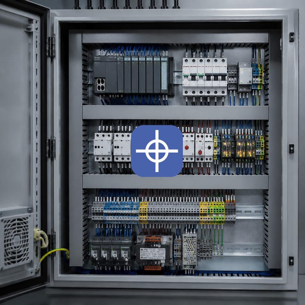
A view inside a CNC electrical panel showing contactors, safety relays, field terminals, the power supply, transformer, and cooling fans.
Conclusion
Building a standard electrical panel isn’t just about choosing reliable equipment. Even the best switch, PLC, or drive can’t perform reliably if the layout is poor, ventilation is weak, grounding is incomplete, wiring isn’t done properly, or power and control circuits aren’t separated.
To achieve a safe, reliable electrical panel, the following must be addressed together:
- Choosing the right standard
- Correctly calculating current and short-circuit values
- Selecting an enclosure suited to the environment
- Determining the appropriate protection rating
- Thermal management
- Zoned layout
- Separating power, control, and signal
- Proper grounding and shielding
- Adequate circuit protection
- Numbering and documentation
- Carrying out pre-delivery tests
For industrial implementation, explore Radonix PC-based CNC controllers, control software and machine-specific HMI systems. Radonix PC-based CNC controller systems.