


Table of Contents
- Introduction
- Definition and Role of the Spindle in CNC Machines
- Structure and Main Components of the CNC Spindle
- Classification of CNC Spindles
- Key Parameters in Selecting a CNC Spindle
- Applications of the CNC Spindle in Industry and Automation
- Installation and Operation Requirements
- Maintenance and Periodic Inspection Tips
- Conclusion
- References and Further Reading
1. Introduction
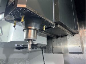
The CNC spindle is one of the most vital components of machine tools, especially CNC machines. The accuracy, machining surface quality, production speed, and reliability of a machine depend directly on the correct performance of the CNC spindle. In fact, a CNC spindle is the rotation-generating unit that turns the cutting tool or workpiece at a specific speed and torque, forming the foundation of the chip-removal and shaping process.
2. Definition and Role of the Spindle in CNC Machines
In CNC milling, engraving, stone, and wood machines, as well as many automation equipment, the CNC spindle acts as the rotation axis of the tool. The cutting tool (drill, milling cutter, engraving blade, etc.) is installed inside the tool-holder system of the CNC spindle and rotates at high speed.
In some machines, such as lathes, the CNC spindle also serves as the rotation axis of the workpiece (together with a suitable chuck or collet).
The main tasks of the CNC spindle are as follows:
- Providing stable and uniform rotation at a controlled speed
- Delivering sufficient torque appropriate to the type of operation and the material of the workpiece
- Holding the tool or workpiece precisely and safely
- Transmitting cutting force to the workpiece with minimum vibration and deviation
The correct performance of the CNC spindle directly affects dimensional accuracy, final surface quality, tool life, and production-line efficiency.
3. Structure and Main Components of the CNC Spindle
An industrial CNC spindle consists of several key subsystems that are assembled together as a single, precise, integrated unit:
3.1. Housing / Body
- A metal shell (usually aluminum or alloy steel)
- The mounting location for the bearings, windings, cooling channels, and the connection point to the carriage or machine frame
- Equipped with the grooves and threads required for mounting brackets, cooling fittings, and the tool-holder system
3.2. Spindle Shaft
- The main rotation axis on which the tool holder of the spindle is mounted
- Ground and balanced with high precision to minimize vibration
- Its mechanical strength and hardness play an important role in withstanding cutting forces
3.3. Bearing Assembly
- Usually angular-contact bearings with a high precision class are used
- Responsible for withstanding radial and axial loads and ensuring rotational accuracy
- The quality, lubrication type, and correct assembly of the bearings are among the main factors affecting the CNC spindle’s life and accuracy
3.4. Drive Unit (Motor / Stator & Rotor)
- In electric spindles, the stator (windings) is installed in the housing and the rotor on the shaft
- Power is usually supplied through a variable-frequency drive (VFD) / inverter
- Main specifications: rated power (kW), rated speed (rpm), rated current, and supply voltage
3.5. Cooling System
- Air Cooled: uses an internal fan and a heat sink on the housing to dissipate heat.
- Water Cooled: water flows through channels in the housing and transfers heat to the cooling circuit (tank, pump, radiator, or chiller).
The choice of cooling method for a CNC spindle depends on the duty cycle, environment, and load type.
3.6. Tool Holder / Collet System
- The most common system in light- to medium-duty spindles is the ER collet series (such as ER11, ER16, ER20, ER25, ER32, etc.).
- The tool is placed inside the collet and tightened with a special nut.
- More advanced spindles use special holders and an automatic tool changer (ATC).
4. Classification of CNC Spindles
4.1. By Cooling Method
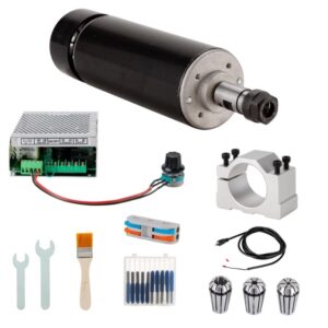
- Air-Cooled Spindle
- Equipped with a fan and heat sink
- Simpler installation, no need for a water circuit
- Suitable for jobs with medium or short operating time
- Easier maintenance, but noisier than the water-cooled type
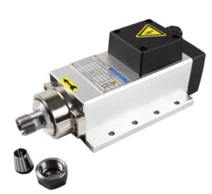
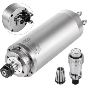
- Water-Cooled Spindle
- Has water-flow channels in the housing
- Lower operating noise and the ability to run continuously under higher loads
- Suitable for industrial CNC machines with long duty cycles
- Requires a pump, tank, hose, and, if needed, a radiator or chiller
4.2. By Power Transmission Method
- Direct-Drive Spindle
- The motor rotor is mounted directly on the spindle shaft.
- High efficiency, low vibration, and high accuracy.
- Common in modern CNC machines for wood, aluminum, and light/medium milling.
- Belt-Driven Spindle
- The motor is separate, and power is transmitted through a belt and pulley.
- The speed ratio can be changed by swapping pulleys.
- Common in more traditional machines and certain specific applications.
- Gear-Driven Spindle
- Uses a gearbox between the motor and the spindle shaft.
- Suitable for applications that require very high torque at relatively low speeds (heavy pressing, large hard-metal milling).
4.3. By Application Area
- Wood and MDF CNC Spindle
- High speeds (usually 18,000 to 24,000 rpm)
- Power varying between 1.5 and 9 kW
- Suitable for cutting, engraving, routing, and tooling on wood, MDF, PVC, acrylic, and similar materials
- Stone CNC Spindle
- Reinforced structure, larger collets, higher power and torque
- Suitable for cutting, profiling, and engraving natural and industrial stone
- Fine, High-Speed Engraving Spindle
- Lower power (about 300 W to 1 kW)
- Very high speed (sometimes up to 30,000-60,000 rpm)
- Used for fine engraving, PCB work, small parts, and precision mold making
- Metal Machining Center Spindle
- High accuracy and strength, often equipped with an automatic tool-changer system
- Suitable for milling, drilling, tapping, and machining steel, aluminum, and alloys
5. Key Parameters in Selecting a CNC Spindle
The following specifications are essential when selecting and evaluating a CNC spindle:
- Rated Power
- Indicates the spindle’s ability to withstand cutting loads under standard operating conditions.
- For light and engraving operations: 0.8 to 2.2 kW
- For heavier cutting on wood, stone, or metal: 3 to 9 kW and above
- Rotation Speed (RPM)
- The adjustable speed range set by the inverter (minimum/maximum speed).
- Soft materials generally require higher speed, while hard metals need lower speed but higher torque.
- Torque
- Determines the spindle’s ability to maintain the desired speed under heavy cutting load.
- In metalworking and deep-cutting applications, torque at low speeds is especially important.
- Tool Holder Type and Size
- Determines the range of tool diameters that can be mounted and the strength of tool retention.
- Choosing the correct collet (ER) or holder directly affects vibration, accuracy, and tool life.
- Voltage and Power Supply Type
- Single-phase or three-phase, rated voltage (220V, 380V, etc.), and the need for a suitable inverter.
- Matching the spindle’s rated current with the inverter’s output capacity is essential.
- Cooling Type and Environmental Conditions
- Choosing between air-cooled and water-cooled depends on operating duration, load type, ambient temperature, and workshop constraints.
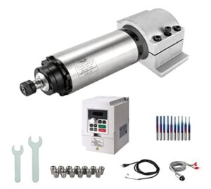
6. Applications of the CNC Spindle in Industry and Automation
The CNC spindle is used in a wide range of equipment and production lines:
- Wood and MDF CNC Machines
- Cutting cabinet panels, doors, decorations, furniture, 3D signage, and artistic designs.
- Used in high-precision, high-speed serial production lines.
- Metal CNC Machines
- Producing industrial parts, molds, automotive components, industrial equipment, and more.
- Operations such as milling, drilling, face milling, and tapping.
- Stone and Facade CNC Machines
- Producing kitchen counters, tombstones, decorative parts, and building facades.
- Requires durable spindles with sufficient power and torque.
- Special-Purpose Machines
- Multi-axis drilling machines, automatic assembly machines, and dedicated production lines.
7. Installation and Operation Requirements
To achieve stable performance and the desired service life of the CNC spindle, the following installation and start-up guidelines are recommended:
- Correct Mechanical Installation
- Use standard brackets and a completely level, rigid mounting surface.
- Avoid extra stress on the spindle body caused by improper bolting.
- Tool Balance and Alignment
- Use balanced, undamaged tools.
- Ensure correct alignment of the tool with the spindle axis when mounting it in the collet or holder.
- Correct Inverter (VFD) Settings
- Set the frequency and maximum allowed speed according to the spindle’s nameplate specifications.
- Observe current limits and use soft start/stop.
- Cooling System Control
- For water-cooled spindles: ensure continuous, sufficient water flow, no leaks, and the use of clean water or a suitable solution.
- For air-cooled spindles: keep the air path clean and prevent blockage of the cooling vents.
8. Maintenance and Periodic Inspection Tips
Proper maintenance of the CNC spindle directly reduces sudden breakdowns and extends the machine’s useful life:
- Initial Warm-Up
- It is recommended that, at the start of each work shift, the spindle run for a few minutes at medium speed so the bearings reach operating temperature.
- Noise and Vibration Inspection
- Any unusual change in sound (roaring, whistling, severe vibration) can indicate bearing failure, tool imbalance, or loose connections.
- If observed, continuing to operate the spindle is not recommended, and a technical inspection should be carried out.
- Operating Temperature Control
- The CNC spindle housing temperature must remain within the manufacturer’s allowed range.
- Excessive temperature rise indicates poor cooling, overload, or a fault in the inverter or spindle.
- Periodic Cooling System Inspection
- For water-cooled types: check the water level and quality, verify there is no blockage in the channels, and confirm correct pump operation.
- For air-cooled types: clean the fan and heat sink, and prevent dust build-up.
- Tool Holder and Collet Care
- Periodically clean the collet, nut, and tool seating area.
- Avoid using cracked collets or bent/damaged tools.
- Tighten the tool with the proper torque and avoid striking it.
9. Conclusion
The CNC spindle is the core unit of the machining system in CNC machines, and the quality, accuracy, and efficiency of the entire system depend largely on the correct selection, proper installation, and appropriate maintenance of the spindle.
By understanding its internal structure, cooling types, power-transmission methods, selection parameters, and by following operational and periodic-service requirements, it is possible to:
- Improve dimensional accuracy and part surface quality;
- Extend the life of the tool and the CNC spindle;
- Prevent sudden production stoppages and heavy repair costs.
10. References and Further Reading
For those interested in more details about the design, structure, and maintenance of the CNC spindle in CNC machines, the following references are suggested:
- CNC Mill Spindle: Bearings, Belt Drive, VFD, ATC, and Design Notes — CNC Cookbook
- Understanding CNC Spindle — Runsom Precision
- What Is a CNC Spindle? — Setco
- The Ultimate Guide to CNC Machine Tool Spindle Bearings — AUBEARING
- Preventive Maintenance for CNC Spindles: A Checklist for Reliability, A Guide to CNC Spindles and Their Applications — com
- What is a CNC Spindle — CNC Machine Tool Spindle Definition, Types and Uses — com
Author: Mahboubeh Sajjadi