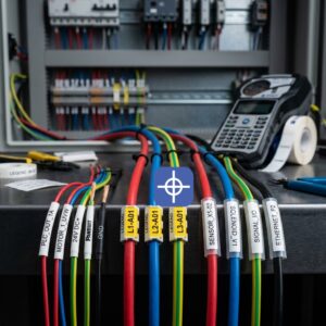


Electrical Wire Labeling Standards: IEC, NEC & EN Explained
Getting conductor identification right is not a stylistic choice — it is a safety and compliance obligation. Electrical wire labeling standards define how conductors are coloured, marked, and documented so that anyone working on an installation can identify a phase, neutral, or protective earth (PE) conductor correctly and safely. Follow them and your panel passes inspection, protects the people who service it, and reads consistently across borders. Ignore them and you risk failed sign-off, dangerous misidentification, and rework.
The complication is that there is no single global rulebook. A machine built in Europe follows IEC and EN conventions; the same machine exported to the United States is judged against the National Electrical Code; a UK installation answers to BS 7671. The colour that means “neutral” in one system can mean something else — or nothing defined — in another.
This article explains the four frameworks an engineer most often has to satisfy — IEC 60445, NEC Article 310 (and its companion articles), EN 60204-1, and BS 7671 — sets their colour rules side by side, and shows how to apply them in practice. Where a specific requirement depends on the edition of a standard or the authority having jurisdiction (AHJ), that is flagged, and you should always confirm against the current published document.
IEC 60445 — Conductor and Terminal Identification
IEC 60445 is the international basic-safety standard for the identification of equipment terminals, conductor terminations, and conductors. It establishes the general principles: conductors may be identified by colour, by alphanumeric marking, or by a combination, and certain colours are reserved for safety-critical roles.
Two reservations are effectively universal in the IEC system and appear throughout the electrical wire labeling standards that build on it:
- Protective earth (PE): green-and-yellow, reserved exclusively for the protective conductor and never used for any other purpose.
- Neutral: blue (light blue), and light blue should not be used for another conductor where confusion is possible.
For line conductors, IEC 60445 permits identification by colour or alphanumeric designation. The familiar harmonised line colours used across Europe — brown, black, and grey for the three phases — come from the CENELEC harmonisation document HD 308 and are adopted into national wiring rules rather than fixed by IEC 60445 itself. IEC 60445 also covers terminal marking, so the designation on a terminal matches the conductor and the drawing. The standard has been revised over the years (for example, editions in 2017 and 2021), so cite the current edition for formal specification work.
NEC Article 310 — Conductor Identification in the US Context
In the United States, conductor identification lives within the National Electrical Code (NFPA 70). Article 310 covers conductors for general wiring — their construction, insulation, ampacity, and surface markings — and its identification provisions act largely as a roadmap that points to the articles carrying the specific colour rules. This is the key structural difference from the IEC world: the US framework mandates fewer colours and distributes the rules across several articles.
What the NEC actually mandates by colour is narrow but strict:
- Grounded (neutral) conductor: a continuous white or grey finish (or the permitted stripe/marking alternatives), per Article 200.6.
- Equipment grounding conductor: green, green with one or more yellow stripes, or bare, per Article 250.119. Green and green-and-yellow may never be used for an ungrounded or grounded conductor.
Crucially, the NEC does not prescribe specific colours for ungrounded (“hot”) conductors. It requires only that they be distinguishable from grounded and grounding conductors and, where a premises has more than one voltage system, that each ungrounded conductor be identified by phase and system at all termination points (Article 210.5(C)), with a legend posted at the panelboard. The widely used palettes — black/red/blue for 120/208 V and brown/orange/yellow for 277/480 V — are de-facto industry conventions, not code requirements. One colour rule for a hot conductor is codified: the high-leg of a high-leg delta system must be orange (Article 110.15). Because the NEC is revised on a three-year cycle and adopted state by state, always confirm the edition your AHJ enforces.
EN 60204-1 — Wiring of Machinery and Control Panels
EN 60204-1 (the European harmonised version of IEC 60204-1), “Safety of machinery — Electrical equipment of machines,” governs the wiring inside machine control panels rather than fixed building installations. It is the standard most relevant to panel builders and machine integrators.
For safety-critical conductors it is firm: the protective conductor must be green-and-yellow, and where a neutral is identified by colour it must be light blue. For other conductors, the standard is deliberately permissive — it uses “may be” language — and recommends the following insulation colour scheme:
- Black: AC and DC power circuits
- Red: AC control circuits
- Blue: DC control circuits
- Orange: excepted circuits — those that may remain energised from an external source when the machine’s main disconnect is off
Note that EN 60204-1 does not assign a separate colour to each phase. Power conductors are typically all black and distinguished by number or alphanumeric marking, which is why disciplined conductor marking matters so much in machinery. The standard also requires that terminals on terminal blocks be marked to correspond with the diagrams, tightly coupling the physical marking to the documentation. As with the others, edition matters (recent editions include 2018), so specify against the current version.
BS 7671 — UK Wiring Colour and Marking Requirements
BS 7671, the IET Wiring Regulations, governs fixed electrical installations in the UK and uses the CENELEC harmonised colours. Since the harmonisation transition (harmonised colours were introduced from 2004 and became mandatory for new work from 2006), UK installations follow:
- Single-phase AC: line brown, neutral blue, PE green-and-yellow.
- Three-phase AC: L1 brown, L2 black, L3 grey, neutral blue, PE green-and-yellow.
BS 7671 focuses on identifying the function of a conductor — line, neutral, protective — and allows identification by the harmonised colours or, where appropriate, by alphanumeric marking (for example, on numbered black cores). It also addresses the practical reality of legacy installations: where old and new colour codes meet, warning notices are required at the interface so that the change of convention is unmistakable. A conductor’s role can additionally be indicated by its position (for example, at a busbar) rather than colour alone, provided identification is unambiguous.
Electrical Wire Labeling Standards Side by Side
The table maps the core roles across the four frameworks. It is a general reference, not a substitute for the published standards; where a cell notes “convention,” that colour is customary practice rather than a mandated requirement.
| Conductor role | IEC 60445 / harmonised (Europe) | NEC (US) | EN/IEC 60204-1 (machinery) | BS 7671 (UK) |
| Protective earth (PE) | Green-and-yellow | Green, green/yellow stripe, or bare | Green-and-yellow (required) | Green-and-yellow |
| Neutral | Blue (light blue) | White or grey | Light blue | Blue |
| Line (single-phase) | Brown | Not mandated (convention: black) | Black (power circuit) | Brown |
| L1 / L2 / L3 (three-phase) | Brown / black / grey | Not mandated (convention: black-red-blue at 208 V; brown-orange-yellow at 480 V) | Black; phases distinguished by marking | Brown / black / grey |
| AC control circuit | By marking/colour | Not mandated | Red | By marking |
| DC control circuit | By marking/colour | Not mandated | Blue | By marking |
| Externally-supplied / excepted | By marking | Orange (high-leg delta, 110.15) | Orange | By marking |
Where they align: green-and-yellow for protective earth is effectively universal, and the IEC-derived systems (IEC 60445, EN 60204-1, BS 7671) agree on blue/light-blue for neutral and reserve green-and-yellow strictly for PE.
Where they differ: neutral is the classic trap — light blue in the IEC world but white or grey under the NEC. Line-conductor colour is prescribed in the European systems (brown/black/grey) but left to convention in the US. And EN 60204-1 identifies phases by marking rather than per-phase colour, unlike BS 7671’s fixed brown/black/grey. These differences are exactly why export machines demand careful attention.
Applying the Standards in Practice
Knowing the colours is only half the job; compliant identification also has to be durable, legible, and documented.
Identify at every termination. All the frameworks share a common principle: a conductor must be identifiable where it terminates. In practice that means marking both ends of a run so the conductor can be traced without a meter.
Match marking to documentation. EN 60204-1 and IEC 60445 explicitly require terminal marking to correspond with the diagrams. The identifier on the wire, the terminal designation, and the schematic must agree, which makes as-built documentation part of compliance rather than an afterthought.
Specify durability for the environment. A compliant colour that fades or an alphanumeric mark that rubs off is no longer compliant. UL 969 is commonly referenced in the US for the durability and permanence of marking and labels; more generally, the marking must remain legible for the service life of the conductor under the expected heat, oil, UV, and abrasion.
Handle mixed conventions deliberately. Where old and new colour codes coexist (common in UK refurbishments), post the required warning notices. On export machines, resolve the neutral-colour conflict before wiring, not after inspection.
For the practical decision of how to physically mark conductors — printed labels, sleeves, or tags — see our comparison of methods in the wire labeling system guide, and for the logic that determines what each identifier says, see the cable numbering system guide. This article covers the standards that govern both.
How Radonix Wire Tags Support Standard-Compliant Marking
Standards define the requirement; the marking on the conductor is what demonstrates it. Radonix wire tags are built to carry standard-compliant identification into the panel, whichever framework your project answers to.
Because the tags support both colour identification and clear alphanumeric marking, they accommodate the two identification methods the standards recognise — colour for conductor function and alphanumeric for phase, circuit, or terminal designation. That flexibility matters on machinery wired to EN 60204-1, where phases are distinguished by marking rather than colour, and on export builds where the same machine must satisfy IEC-derived and NEC identification at once.
Radonix wire tags align with the identification and durability practices these standards expect — green-and-yellow reserved for PE, blue for neutral in IEC systems, and legible, permanent marking consistent with IEC 60445 terminal and conductor identification and UL 969-style durability. Just as importantly, they let the tag on the wire match the terminal designation and the drawing, which is where compliance is ultimately judged. They are one well-suited option among several on the market; the right choice is the marking that meets your governing standard and survives your environment.
FAQ
What is the difference between IEC and NEC neutral colours?
This is the most important cross-standard difference to remember. In IEC-based systems (IEC 60445, EN 60204-1, BS 7671) the neutral is blue or light blue. Under the US NEC, the grounded (neutral) conductor is white or grey. Blue is not a neutral colour in the NEC, and white/grey is not a neutral colour in the IEC world — a genuine hazard if the two are confused on an international project.
Which standard applies to a control panel versus a building installation?
For the electrical equipment inside machinery and control panels, EN 60204-1 (IEC 60204-1) is the relevant standard. For fixed building installations, it is BS 7671 in the UK or the NEC in the US, with IEC 60364 as the international reference. A machine installed in a building may involve more than one, so identify which governs which part of the work.
Is green-and-yellow always protective earth?
In every IEC-based system, yes — green-and-yellow is reserved exclusively for the protective conductor and must never be used for anything else. Under the NEC, the equipment grounding conductor is green, green-with-yellow-stripe, or bare, and those finishes likewise cannot be used for ungrounded or grounded conductors. Treat green-and-yellow as protective earth universally and never repurpose it.
How do I label conductors on a machine exported to the US?
Resolve the neutral conflict first: an IEC-wired machine using light-blue neutral must be reconciled with NEC expectations for the installation side, and multi-voltage systems require each ungrounded conductor to be identified by phase and system with a posted legend. Confirm the specific requirements with the AHJ for the destination, and use clear alphanumeric marking to bridge the conventions unambiguously.
Do the standards mandate specific hot/line conductor colours? It depends on the framework. The European systems prescribe brown/black/grey for the three phases. The NEC does not mandate colours for ungrounded conductors — the common palettes are convention — though it does require them to be distinguishable from neutral and ground, and mandates orange for the high-leg of a high-leg delta.
Get Compliant Marking on Every Conductor
Meeting the relevant electrical wire labeling standards comes down to a disciplined sequence: identify which framework governs your work, apply the reserved colours correctly — green-and-yellow for PE, the right neutral colour for the system — mark phases and circuits clearly where colour alone is not prescribed, and keep every identifier consistent with the drawings and durable for the life of the installation. Always verify against the current edition of the standard and your AHJ.
When you need marking that carries that compliance onto the wire, explore Radonix wire tags for colour and alphanumeric identification that maps to your governing standard — or contact the Radonix team for guidance on marking your build to spec.
For industrial implementation, explore Radonix PC-based CNC controllers, control software and machine-specific HMI systems. Radonix PC-based CNC controller systems.