What Is CAD/CAM and How Is It Used in Industry?
Written by: Nima Rad
CAD/CAM—often referred to in industry as “CADCAM” or informally “Codecam”—represents the integration of Computer-Aided Design (CAD) and Computer-Aided Manufacturing (CAM) into a single, continuous workflow. The goal is to move efficiently and reliably from idea → digital model → manufacturing program → physical production on a CNC machine, while minimizing errors and manual intervention.
In modern industrial environments, CAD/CAM is not a convenience tool; it is a foundational layer of digital manufacturing that directly affects accuracy, repeatability, productivity, and long-term process stability.
1. What Does CAD/CAM Mean in Practical Industrial Terms?
CAD and CAM address two distinct but tightly connected stages of manufacturing.
CAD (Computer-Aided Design) is responsible for defining what must be manufactured. It covers the creation of 2D drawings and 3D models, assemblies, geometric constraints, tolerances, and design intent. CAD establishes the authoritative digital definition of the part.
CAM (Computer-Aided Manufacturing) defines how that design is produced. CAM software converts CAD geometry into manufacturing strategies by selecting tools, defining machining operations (milling, turning, 5-axis machining, etc.), generating toolpaths, and preparing outputs suitable for CNC execution.
In industrial practice, CAM systems almost always include simulation and verification stages. These simulations are used to detect tool or holder collisions, excessive loads, and path errors before code reaches the machine—reducing scrap, downtime, and risk.
2. How CAM Output Becomes CNC Machine Language
Toolpaths generated inside CAM software are not directly executable by CNC machines. They must first be translated into a controller-specific language—most commonly G-code. This translation is performed by a post-processor.
A post-processor converts generic CAM output into the exact syntax, cycles, axis definitions, and motion behaviors expected by a specific CNC controller and machine configuration. This step is critical: even identical machines may require different post-processors depending on controller brand, kinematics, and options.
A typical industrial CAD/CAM workflow follows a structured sequence:
- CAD modeling of the part or assembly
- Definition of raw material, fixtures, work offsets, and orientations
- Selection of machining strategies (2.5D, 3-axis, 5-axis, turning, mill-turn, etc.) and cutting tools
- Toolpath generation and cutting parameter validation
- Simulation and verification to prevent collisions and logic errors
- Post-processing to generate machine-specific G-code
- Production, followed by feedback for process or design refinement
This closed-loop workflow supports continuous improvement without breaking digital traceability.
3. Industries Where CAD/CAM Is Most Widely Applied
CAD/CAM is essential in industries where precision, repeatability, and complex geometry are unavoidable requirements:
- CNC machining: milling, turning, mill-turn, and simultaneous 5-axis operations
- Mold and die manufacturing: complex surface generation and high-quality finishes
- Aerospace, automotive, and medical manufacturing: tight tolerances, process traceability, and advanced geometries
- Cutting technologies such as laser, waterjet, and plasma, which are directly supported by many CAM platforms
In these sectors, CAD/CAM is not optional—it defines production capability.
4. Well-Known CAD/CAM Software Platforms and Ecosystems
Integrated CAD + CAM Platforms
Some systems provide tightly coupled CAD and CAM environments:
- Autodesk Fusion: A cloud-enabled CAD/CAM/CAE platform widely used for agile development and small-to-mid-scale production
- Siemens NX: An enterprise-grade CAD/CAM solution with advanced NC programming and industrial simulation capabilities
- CATIA / DELMIA (Dassault Systèmes): CATIA focuses on advanced design, while DELMIA addresses CAM, simulation, and manufacturing optimization at scale
- PTC Creo: A CAD platform with integrated CAM tools suited for teams seeking a unified environment
Specialized CAM Systems for CNC Machining
Other solutions focus primarily on CAM performance and flexibility:
- Mastercam: One of the most widely adopted CAM systems for toolpath generation across diverse machining scenarios
- PowerMill (Autodesk): Advanced CAM software for complex, high-speed, and 5-axis machining applications
- hyperMILL (OPEN MIND Technologies): A modular CAM system supporting 2.5D through advanced multi-axis machining
- Hexagon CAM solutions (e.g., EDGECAM): CAM platforms covering milling, turning, and multi-axis CNC programming
CAM Integrated Within CAD Environments
- SOLIDWORKS CAM: CAM functionality embedded within the SOLIDWORKS CAD environment
- CAMWorks: Feature-based CAM tightly integrated with SOLIDWORKS
- SolidCAM: Integrated CAM with full associativity—toolpaths automatically update when the CAD model changes
5. Radonix CAD/CAM Solutions in Practice
Radonix approaches CAD/CAM from a controller-centric, industrial execution perspective.
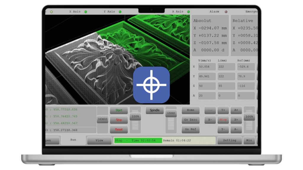
Radonix CAM-Pro is the primary CNC control and execution software used alongside Radonix controllers. While it is sometimes described as a CAD/CAM solution, its industrial role is best defined as NC control and execution, rather than full CAD modeling.
Key characteristics include:
- Compatibility with PC Pro-LAN and PC Smart controller families
- Support for up to 6 simultaneous axes
- Acceptance of standard inputs such as G-code and DXF, enabling execution of output from external CAD/CAM systems
- Operator-focused capabilities including customizable interfaces, motion and path visualization, monitoring, alarms, and diagnostics
Radonix documentation also references earlier software families such as RadonixCAM and RadonixCAM+, which represent previous generations of Radonix operational and control software. CAM-Pro is positioned as the more current and actively developed solution.
To support commissioning, calibration, and validation, Radonix provides auxiliary tools for CAM-Pro, including axis calibration utilities, testing modules, setup and security tools, and joystick and control-status features. In addition, Radonix offers interfaces and post-processors that bridge external CAD/CAM outputs with its CNC controllers.
Conclusion
CAD/CAM is not a single tool or product—it is a digital manufacturing framework that connects design intent to physical production. In modern CNC environments, its effectiveness depends on accurate modeling, robust toolpath generation, reliable post-processing, and tight integration with the CNC controller.
Radonix’s CAD/CAM-related solutions focus on the execution layer of this framework, enabling industrial users to reliably run outputs from leading CAD/CAM platforms while maintaining deterministic control, operational transparency, and long-term system stability.
Contact Radonix or use the chatbot in the bottom right corner to learn how linear encoders integrate with Radonix control systems.