
Servo Motor in CNC Machines: Complete Technical Guide for Selection, Tuning, and Performance
Author: Nima Rad – Radonix Automation
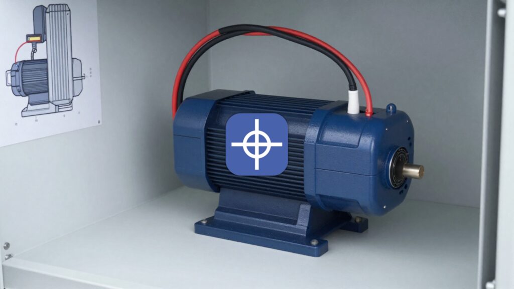
What Is a Servo Motor?
In industrial automation—especially CNC systems—a servo motor is an electric motor integrated with a feedback device (position and/or speed sensor) and controlled by a servo drive operating in a closed-loop architecture.
This closed-loop system continuously measures actual performance and corrects torque, speed, and position in real time. The result is:
- High positional accuracy
- Fast dynamic response
- Stable torque across a wide speed range

A typical CNC servo axis consists of:
1. Servo Motor
Most commonly Permanent Magnet Synchronous Motors (PMSM) or industrial BLDC motors.
2. Feedback Device
- Incremental encoder
- Absolute encoder
- Resolver (for harsh environments)
- Linear scale (for direct table position feedback in high-precision CNC systems)
3. Servo Drive (Amplifier)
Includes inverter stage, current/speed/position controllers, protection circuits, and industrial communication interfaces.
4. CNC/PLC Controller
Generates trajectory commands including:
- Target position
- Target speed
- Acceleration and jerk profile
- Multi-axis coordination
Why Servo Motors Are Dominant in CNC Applications
Servo systems are preferred in professional CNC machines due to several performance advantages:
True Closed-Loop Position Control
Compensates automatically for load changes, friction, voltage variations, and temperature effects.
High Bandwidth Response
Critical for sharp corners, sudden trajectory changes, and vibration control.
High Low-Speed Torque with Overload Capability
Typical overload capacity can reach 200% for short durations.
Accuracy Under Variable Load
Maintains positioning precision even when driving heavy tables, gearbox systems, or servo spindles.
Common Types of Servo Motors in Industry
By Motor Technology
AC Servo (PMSM / Brushless)
Most common in CNC and robotics. High efficiency and low maintenance.
Brushed DC Servo
Older technology requiring brush maintenance. Still found in legacy systems.
Linear Servo Motor
Provides direct linear motion. High speed and precision with higher system cost.
By Feedback Type
Incremental Encoder
Typically requires homing after power-up.
Absolute Encoder
Retains position data; enables faster and safer restart.
Resolver
More resistant to heat and electrical noise.
Inside the Servo Drive: Cascaded Control Loops
Industrial servo drives typically use cascaded control architecture:
Current (Torque) Loop – Fastest
Controls motor phase currents to produce precise torque.
Velocity Loop
Maintains commanded RPM and compensates for load disturbances.
Position Loop – Outermost
Ensures the axis reaches target position with minimal error and overshoot.
Inner loops operate at higher sampling frequencies and determine overall system responsiveness.
Key Servo Motor Specifications You Must Understand
Torque Ratings
- Rated Torque: Continuous torque without overheating
- Peak Torque: Short-duration overload capability
- Holding Torque at Zero Speed: Maintained via current loop control
Speed Ratings
- Rated speed
- Maximum speed
Mechanical limits (bearings, rotor balance) and electrical limits (bus voltage, back EMF) must both be evaluated.
Inertia Considerations
- Motor inertia (Jm)
- Load inertia (Jl)
The inertia ratio (Jl/Jm) significantly affects stability and tuning complexity.
Practical guideline: keeping inertia ratio below 5–10 simplifies control and improves robustness.
Encoder Resolution
Typical encoder resolutions: 17-bit to 23-bit.
Linear positioning accuracy depends on screw pitch, pulley ratio, or gearbox reduction.
Practical Servo Sizing for a CNC Axis
Servo sizing must begin from mechanical analysis.
Required Torque Calculation
Acceleration torque:
T_acc = J_total × α
Load torque:
T_load ≈ F × r
or derived from ball screw force-to-torque conversion.
Vertical axes (Z-axis) require gravity compensation and often:
- Holding brake
- Mechanical counterbalance
RMS Torque Verification
Motor selection must consider RMS torque over the real duty cycle—not only peak values.
If RMS torque exceeds rated torque, overheating will occur even if peak events are brief.
Voltage and Speed Matching
Verify that:
- Required speed lies within motor torque curve
- Drive bus voltage (e.g., 220VAC or 380VAC class) is properly selected
Feedback Selection
- Absolute encoder for fast recovery and high reliability
- Resolver or enhanced shielding for noisy industrial environments
Servo Tuning: Why Some Axes Oscillate or Whine
Improper tuning leads to:
- Oscillation at standstill
- Overshoot during direction change
- Resonance noise
- High following error
Key adjustable parameters include:
- Position gain (Kp)
- Velocity loop gains (Kp, Ki)
- Velocity and acceleration feedforward
- Notch filters for resonance suppression
- Inertia identification / auto-tuning
- Torque limits
- S-curve / jerk control
Important principle:
Software tuning cannot compensate for poor mechanics. Backlash, weak couplings, misaligned screws, or low-quality bearings must be corrected mechanically first.
Servo vs Stepper in CNC Systems
| Feature | Servo | Stepper |
|---|---|---|
| Feedback | Closed-loop | Typically open-loop |
| High-speed torque | Strong | Drops significantly |
| Accuracy under load | High | Risk of step loss |
| Tuning | Required | Simpler |
| Cost | Higher | Lower |
| Professional CNC use | Excellent | Entry-level/light duty |
Wiring and EMC Best Practices
Many servo issues originate from electrical noise and grounding problems.
- Separate motor and encoder cable routing
- Proper shield grounding at drive side
- Use EMI filters or line chokes if required
- Ensure proper grounding of motor body, cabinet, and drive
- Design safe and reliable brake circuits for vertical axes
Recognized Servo Brands and Ecosystems
Major industrial ecosystems include:
- Yaskawa
- Mitsubishi Electric
- FANUC
- Siemens
- Allen-Bradley
- Beckhoff
- Delta Electronics
- Panasonic
- HEIDENHAIN
Selection should consider ecosystem compatibility, service availability, and integration with CNC controller architecture.

Quick Checklist for Selecting a CNC Servo Axis
- Motion mechanism type (ball screw, rack & pinion, belt, gearbox)
- Load mass and inertia
- Required speed and acceleration
- RMS and peak torque validation
- Mechanical RPM limits and backlash
- Required encoder type and resolution
- Drive voltage class and regeneration handling
- EMC and wiring quality
- Safety requirements (STO, brake for Z-axis)
Servo motors remain the backbone of high-performance CNC machines. Correct selection, proper mechanical design, accurate sizing, and disciplined tuning determine whether a CNC axis performs with precision and stability—or struggles with vibration and positioning errors.