
Linear Guide Rail Selection and Types
Author: Nima Rad
Why Linear Guide Rails and Carriages Are Critical
A linear guide rail is a core structural element in CNC machines and precision motion systems. Its role goes far beyond enabling linear movement.
The selection of the guide rail directly determines how accurately the machine positions, how rigidly it resists cutting forces, and how reliably it maintains performance over time.
On every motion axis (X, Y, and Z), the guide system governs several performance-critical factors:
- Positioning accuracy and repeatability over long production cycles
- Structural rigidity and resistance to bending and torsion
- Static and dynamic load capacity, including moment loads
- Speed and acceleration behavior during direction changes
- Service life under wear and fatigue
- Resistance to contamination such as chips, dust, coolant, and plasma debris
For these reasons, a linear guide rail should be viewed as the backbone of axis precision and durability, not merely a mechanical accessory.
Main Components and Key Terminology
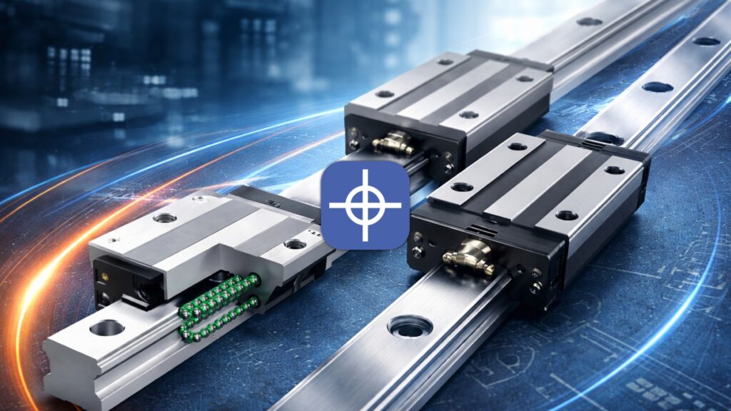
Understanding the structure of a linear guide system is essential before attempting any sizing or selection. A typical system consists of a hardened steel rail with precision-ground raceways and one or more carriages that move along it. Inside each carriage, rolling elements circulate continuously to support the applied loads while maintaining smooth motion.
The main components of a linear guide system are:
- Rail – hardened steel profile with precision raceways
- Carriage (block) – houses rolling elements, recirculation paths, and sealing systems
- Rolling elements – balls or rollers that carry the applied loads
- Seals, scrapers, and covers – protection against contamination
- Lubrication points – grease nipples or ports for controlled lubrication
When reviewing manufacturer catalogues, engineers must also evaluate several key parameters:
- Dynamic load rating (C) and static load rating (C0)
- Moment ratings (Mx, My, Mz) for bending and torsional loads
- Preload level, defining internal clearance and stiffness
- Accuracy class (such as N, H, P, SP, UP, depending on manufacturer)
- Clearance class (C0, C1, Z0, ZA, etc.)
- Nominal rail size, commonly 15, 20, 25, 30, 35, 45 and above


Types of Linear Guide Rails by Technology
Linear guide rails are primarily categorized by the type of rolling element used. The choice between ball-type and roller-type technology has a major impact on stiffness, load capacity, and sensitivity to installation quality.
Ball-type linear guide rails are the most commonly used solution in CNC and automation systems. Their rolling balls provide low friction and smooth motion, allowing high travel speeds with relatively low drive force. This makes them suitable for woodworking CNC machines, laser systems, packaging equipment, and general-purpose CNC axes where loads are moderate and speed is important. The trade-off is lower rigidity and reduced shock resistance compared to roller-based systems, which makes careful protection and maintenance more important.
Roller-type linear guide rails use cylindrical rollers instead of balls. This increases the contact area between rolling elements and raceways, resulting in significantly higher rigidity and better resistance to moment loads and shock. These characteristics make roller guides the preferred choice for heavy CNC machining, machine tools, presses, and high-load robotic systems. However, they require more precise alignment during installation and come at a higher cost.
Miniature linear guides are designed for compact mechanisms with limited space and low loads, such as medical devices or precision instruments. Curved linear guides enable non-linear motion paths and are used only in specialized applications.
Carriage Types and Their Mechanical Impact
The geometry of the carriage has a direct effect on how loads and moments are transmitted into the rail. Short carriages offer compact dimensions and lower moving mass, which can be beneficial for high-speed applications. However, their shorter contact length limits moment capacity.
Long carriages increase the spacing between rolling elements, improving resistance to bending and torsional moments. Flanged carriages simplify mounting and provide a larger contact surface with the machine structure, while non-flanged (square) carriages are used where installation space is limited. Selecting the correct carriage type is often as important as selecting the rail size itself.
Rail Size Selection Based on Application
In early design stages, engineers often rely on practical sizing rules derived from industry experience. Smaller rail sizes are typically sufficient for light-duty machines, while larger sizes are reserved for heavier systems with higher forces and moments.
As a general guideline, rail sizes 15 and 20 are common in light CNC machines and small laser systems. Size 25 is widely used in medium-duty CNC machines, including wood routers and plasma cutters. Sizes 30 and 35 are selected for heavier axes requiring increased stiffness and acceleration capability, while sizes 45 and above are reserved for heavy machine tools and high-load applications.
These rules provide orientation only. Accurate selection always requires an engineering-based evaluation of loads, moments, and layout.
Engineering Method for Selecting a Linear Guide Rail
A reliable selection process starts with defining the real operating loads. This includes the total moving mass of the axis, such as the gantry, spindle, motors, cable chains, and accessories, as well as process forces generated during cutting or operation. Inertial forces resulting from acceleration must also be considered, as they can exceed cutting forces during rapid motion.
Once forces are known, moments must be evaluated. Moments arise whenever forces act at a distance from the rail plane, such as when a spindle is mounted forward of the carriage group on a Z-axis. These moments are often the dominant factor in guide rail selection and are commonly underestimated.
The physical layout of the rails and carriages plays a major role in stiffness. Increasing the distance between parallel rails improves resistance to torsion, while increasing the spacing between carriages on the same rail improves moment capacity. In many cases, optimizing layout is more effective and economical than increasing rail size.
Technology selection follows naturally from the load analysis. Ball-type guides suit general-purpose, high-speed applications with moderate loads, while roller-type guides are chosen for high rigidity and shock resistance. Accuracy class and preload must then be selected based on required precision. Higher preload increases stiffness but also raises friction, heat generation, and sensitivity to misalignment.
Finally, rated life should be verified using manufacturer formulas, which for ball-type guides are commonly proportional to (C/P)³. Environmental conditions must also be addressed through proper sealing, covers, and lubrication, especially in dusty or abrasive environments.
Common Mistakes in Linear Guide Rail Selection
Many guide rail failures are not caused by insufficient load capacity but by design and installation errors. Typical mistakes include underestimating moment loads, selecting larger rails without improving layout, applying excessive preload in poorly aligned structures, and neglecting lubrication and contamination protection. Low-quality rails with poor metallurgy can also lead to early spalling and rapid loss of accuracy.
Installation Considerations
Correct installation is critical to achieving the expected performance from any linear guide rail. Mounting surfaces must be flat and accurately aligned, fasteners must be tightened to specified torque values, and rail parallelism must be controlled using reference edges or locating features. After installation, smooth motion across the full stroke should be verified to detect any localized binding or misalignment.

Application-Based Guidance
In woodworking CNC machines, ball-type linear guide rails in sizes 20 or 25 are commonly used for main axes, with smaller sizes often applied on Z-axes. Plasma CNC machines typically use similar sizes, but sealing and regular cleaning are more critical than rail size due to metal dust. Light to medium metal CNC machines may use size 25 or 30 ball-type guides or roller guides on critical axes. Heavy machine tools rely on roller-type guides with precise installation and controlled lubrication.
Final Selection Checklist
Before finalizing a linear guide rail selection, the designer should confirm moving mass, acceleration, and speed requirements, process forces, moment arms, rail spacing, carriage spacing, environmental conditions, required accuracy, and budget constraints. A systematic review of these factors ensures a reliable, long-lasting selection.
Contact Radonix or use the chatbot in the bottom right corner to learn how linear encoders integrate with Radonix control systems.