Understanding Incremental Encoders in CNC Motion Systems
Written by: Radonix R&D Team.
Incremental encoders are among the most widely used feedback devices in industrial automation, CNC machinery, and precision motion systems.
Their primary function is to convert mechanical rotation into electrical pulses, enabling accurate monitoring of shaft position, direction, and speed in real-time. This makes them essential components in servo drives, CNC axes, and any machine requiring precise closed-loop control.
What Is an Incremental Encoder?
An incremental encoder generates a series of electrical pulses as its shaft rotates. These pulses represent relative movement rather than an absolute position, which makes incremental encoders ideal for applications requiring speed and direction measurement with high resolution.
They are commonly mounted on CNC spindle motors, linear axes (X, Y, Z), robotic joints, and automated production equipment.
The strength of incremental encoders lies in their simplicity, fast response time, and compatibility with a wide range of industrial control systems.
How Incremental Encoders Work
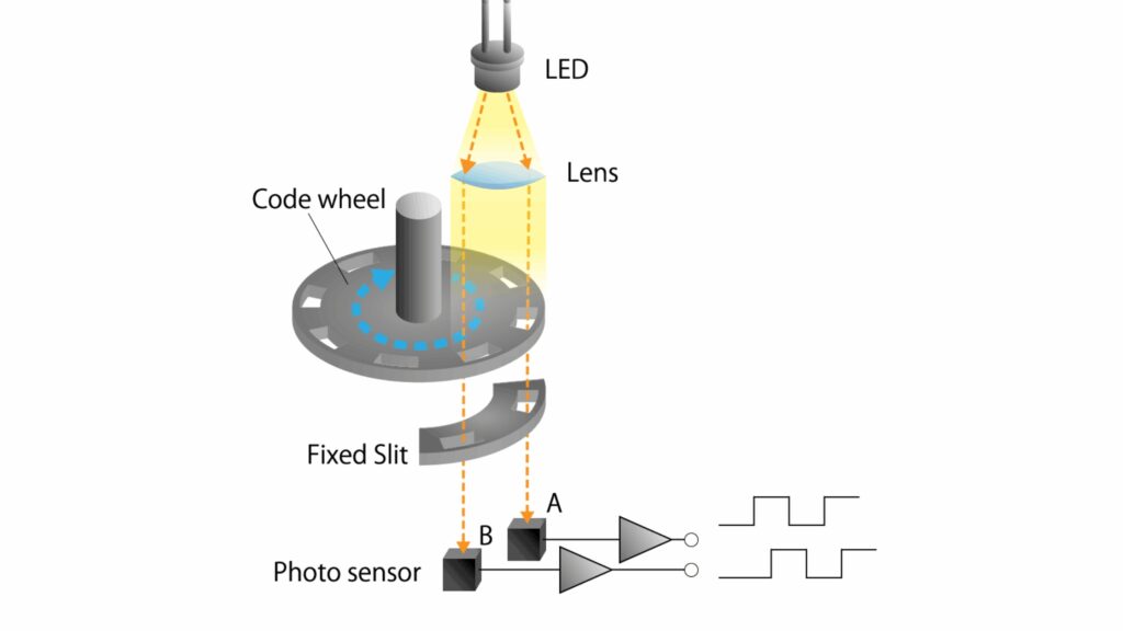
Incremental encoders use a rotating disk marked with transparent and opaque segments. A light source (typically an LED) shines through the disk while a photodetector reads the alternating light pattern.
When the disk moves, the photodetector converts the passing segments into electrical square‑wave signals.
Most incremental encoders output three key signals:
- A pulse–position tracking
- B Pulse – direction detection (A and B have a 90° phase shift)
- Z Pulse (Index) – one reference pulse per revolution for homing
The controller interprets these signals to determine:
- rotational speed,
- angular displacement,
- and direction of rotation.
This simple yet highly effective system has become a foundation of motion control technology worldwide.
Signal Structure and Measurement Principles
The quadrature signals A and B form the core of the incremental encoder operation. Because they are phase‑shifted by exactly 90°, the controller can precisely determine forward or reverse rotation.
The Z signal (also called Index or Marker) creates an electrical reference once per full rotation. CNC machines use this pulse for zero‑setting, homing movements, and restoring accurate machine state after power loss.
A common resolution format is Pulses Per Revolution (PPR), which can range from 100 to 10,000+, depending on the encoder model.
Higher PPR values allow smoother interpolation, higher positioning accuracy, and better servo performance.
Encoder Technology Types
Incremental encoders come in several technology variants. Each is suited for different environmental conditions and machine types.
Optical Encoders
Use LED + photodetector + coded disk.
- Extremely high resolution
- Best accuracy for CNC and metrology
- Sensitive to dust, vibration, oil, and contamination
Magnetic Encoders
Use magnetic poles + Hall effect sensors.
- Resistant to dust, oil, and harsh environments
- Lower resolution than optical types
- Ideal for heavy industrial settings
Inductive Encoders
Use electromagnetic fields to detect position.
- Highly durable in dirty or metallic environments
- Great long‑term stability
- Moderate resolution
These three categories cover 95% of industrial encoder applications.
Electrical Output Types
Different encoders produce different electrical signal formats depending on the controller or drive input requirements.
The main output types include:
- TTL (5V) – high‑speed data transmission
- HTL (10–30V) – noise‑resistant, compatible with industrial automation
- Open Collector – flexible but slower
- Push‑Pull – strong, noise‑tolerant output
- RS‑422 Differential – the preferred standard for CNC systems due to its high noise immunity and stable long‑distance transmission
Choosing the right output type ensures reliable signal integrity under operating conditions.
Resolution and Accuracy
Encoder resolution determines the number of pulses the encoder generates per revolution.
Common values include:
- 1000 PPR – basic automation
- 2500–5000 PPR – high‑quality CNC feedback
- 10,000+ PPR – high‑precision and semiconductor equipment
Higher resolution improves:
- position accuracy,
- motion smoothness,
- and servo loop stability.
CNC machines benefit significantly from encoders with 2500 PPR or higher.
Common Error Sources and How to Reduce Them
Even high‑quality encoders can be affected by technical or mechanical disturbances.
Key error sources include:
1. Jitter
Random timing variations between pulse edges. Caused by electrical noise or LED instability.
2. Phase Error
A and B signals must be 90° apart. Any deviation can cause direction misinterpretation.
3. Signal Drop
Momentary or complete loss of A, B, or Z signals due to: loose connectors, damaged cables, or electrical noise.
4. Mechanical Misalignment
If the encoder shaft is not perfectly aligned with the motor shaft, vibrations and inconsistent pulses appear.
Mitigation Techniques:
- Digital filtering
- Shielded industrial‑grade cables
- Differential RS‑422 signal drivers
- Precision, backlash‑free couplings
These measures ensure stable and accurate long‑term operation.
CNC Applications of Incremental Encoders
Incremental encoders are essential in all CNC machine architectures.
They are commonly used for:
- Axis positioning feedback (X, Y, Z)
- Spindle speed control
- Closed‑loop correction for stepper or servo motors
- Tool alignment and homing routines
The encoder signals allow CNC controllers to:
- correct motion errors instantly,
- maintain consistent toolpaths,
- and ensure micron‑level machining accuracy.
Without incremental encoders, modern CNC performance simply would not be possible.
Installation and Maintenance Guidelines
Correct installation and regular maintenance significantly extend an encoder’s lifespan.
Key recommendations:
- Use backlash‑free flexible couplings
- Keep optical encoders clean and dust‑free
- Ensure shielded cable routing away from power lines
- Confirm tight mounting to avoid shaft vibration
- Inspect connectors regularly
Following these guidelines prevents drift, pulse distortion, and premature encoder failure.
Conclusion
Incremental encoders remain one of the most important components in CNC and automation systems. Their ability to provide accurate, real‑time feedback ensures stable, precise, and reliable machine performance.
By selecting the right encoder type, installing it correctly, and maintaining it properly, manufacturers can greatly improve the accuracy and longevity of their CNC machinery.
This makes the incremental encoder not just a feedback device, but a core part of modern motion‑control engineering.
Contact Radonix or use the chatbot in the bottom right corner to learn how linear encoders integrate with Radonix control systems.