What Every CNC Operator Must Know
Author: Nima Rad
A CNC operator is not merely someone who presses cycle start. In professional manufacturing environments, the operator is directly responsible for converting engineering drawings and CNC programs into accurate, repeatable, and safe parts.
This role requires a clear understanding of machine safety, correct setup, coordinate systems, tooling behavior, quality control, basic maintenance, and effective communication with programmers and supervisors. A skilled CNC operator protects the machine, the tooling, the workpiece, and ultimately the production schedule.
Safety and Workshop Standards
Safety is the first and non-negotiable responsibility of every CNC operator. Unsafe habits are a primary cause of machine damage, tool breakage, and serious injury.
Operators must treat personal protective equipment as a daily requirement:
- Safety glasses and protective footwear at all times
- Hearing protection in high-noise environments
- Gloves only for handling material (never near rotating tools/spindles)
Common hazards that must be actively controlled:
- Flying chips and coolant splash
- Tool fracture or insert breakage
- Loose workpieces inside fixtures
- Entanglement of clothing or hair with rotating components
Lockout/Tagout (LOTO) must be applied during cleaning, servicing, or maintenance. Never place hands inside the machine envelope during automatic motion; remove chips only using brushes or hooks.
Operators must understand and react correctly to emergency systems:
- E-Stop
- Door interlocks
- Feed hold
- Reset and recovery logic

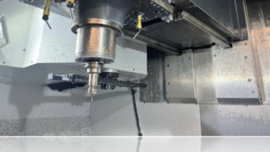
CNC Machine Structure and Core Components
A CNC operator must understand what each major machine component does and how early signs of failure appear. This knowledge enables quick action before small issues become expensive breakdowns.
Core areas to know at the operator level:
- Axes and motion system: X/Y/Z and A/B/C when available; abnormal noise, vibration, backlash, or positioning drift
- Spindle: RPM stability, torque behavior, overheating, and unusual sound
- Servo/stepper drives and encoders: follow error, overload, and feedback-related alarms
- Coolant and lubrication: concentration, filtration, nozzle direction, clogging, and leak detection
- Pneumatic/hydraulic systems (if present): pressure stability for clamps and tool-change systems
- ATC (automatic tool changer): tool order, sensor feedback, and common change faults
- Homing and limits: home/reference behavior, limit switches, and soft limits
Ignoring homing or limit warnings is a common path to collisions.
Coordinates, Offsets, and Zero Setting
Most serious CNC accidents and scrap parts originate from mistakes in coordinates and offsets. Operators must clearly distinguish between machine coordinates and workpiece coordinates.
Key concepts that must be understood and verified before execution:
- Machine coordinate system versus work coordinate system
- Work offsets such as G54 to G59
- Tool Length Offsets (H) and Cutter Radius Compensation values (D)
- Positive and negative Z-axis direction and associated risks
Zero setting methods may include:
- Edge finding
- Touch probes
- Feeler gauges
- Manual measuring tools
- Tool setter plates
Each method must be applied consistently and verified.
In real-world production, three errors account for most crashes:
- Selecting the wrong work offset
- Entering an incorrect tool length
- Defining an incorrect Z reference
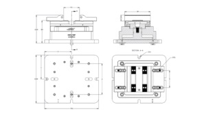
Drawing Interpretation and Dimensional Control
A CNC operator must be able to read technical drawings at an operational level. This includes understanding dimensions, datums, tolerances, surface roughness requirements, chamfers, fillets, and thread standards.
Operators should recognize basic GD&T concepts such as flatness, perpendicularity, concentricity, and positional tolerance. Just as important is identifying the “critical” dimensions that require in-process checks during production.
Delivering an acceptable part is not defined by appearance alone; it is defined by compliance with drawing requirements and repeatable process control.
Tooling Knowledge and Tool Behavior
Tool selection and tool condition directly affect surface quality, dimensional accuracy, and cycle time. Operators should recognize common tool types such as end mills, drills, reamers, taps, inserts, and turning tools, as well as tool materials including HSS, carbide, and coated variants.
Tool holders such as collet chucks, hydraulic holders, and BT/HSK tapers influence runout and rigidity. Excessive tool stick-out increases vibration and breakage risk.
Typical tool wear indicators include edge chipping, discoloration, squealing noise, increased spindle load, and degraded surface finish. When these signs appear, the operator must respond early—continuing to run a worn tool often converts a simple tool change into scrap parts or machine damage.
Feeds, Speeds, and Chip Formation Logic
Operators should understand cutting logic rather than memorizing numbers. Feed rate (mm/min) is not the same as feed per tooth (chip load), which directly controls chip thickness.
High RPM combined with insufficient feed produces thin chips, excess heat, and rapid wear. Excessive feed or depth of cut increases cutting force and leads to chatter, deflection, or tool failure.
Material type, tool diameter, flute count, fixture rigidity, tool length, and coolant delivery all influence stable cutting.
Symptoms of incorrect parameters include chatter marks, built-up edge, burned surfaces, powder-like chips, or blue chips.
G-Code Awareness for CNC Operators
Operators do not need to be full programmers, but they must be able to read and validate CNC programs before execution. Understanding modal commands is essential because many states remain active until explicitly changed.
At the operator level, recognize and verify:
- Motion commands (rapid, feed, arc moves)
- Plane selection
- Unit definitions
- Work offsets (G54–G59)
- Tool compensation (G41/G42/G40) and tool length logic
- Drilling cycles, when used
- Core M-codes controlling spindle, coolant, and stops
Before cutting, operators should be able to locate the first Z movement, the first approach to the part, to
ol changes, stop points, and any subroutines.
Operators should also understand that CAM output depends on the post-processor, which explains why similar parts may generate different-looking programs.
Setup, Workholding, and Repeatability
Workholding is the foundation of accuracy and repeatability. Even a perfectly written program cannot compensate for poor fixturing.
Common workholding methods include:
- Vises and mechanical clamps
- Dedicated or custom fixtures
- Vacuum systems for wood or composite materials
- Chucks for turning operations
Key setup principles every operator must follow:
- Stable three-point support
- Prevention of part distortion during clamping
- Clear chip evacuation paths
- Guaranteed clearance between tools and clamps
- Consistent tightening torque for repeatability
Alignment, parallelism, and shimming may be required to maintain precision. Human error can be reduced through labeling tools and fixtures and strict adherence to setup checklists.
Safe Execution and Process Monitoring
Professional execution begins with verification. Tools must match the program list, offsets must be checked, and dry runs should be performed at a safe Z height. Initial cutting should be done using single-block mode with reduced feed.
The first article must be inspected and documented. During production, operators must continuously monitor cutting sound, spindle load, coolant flow, chip shape, and critical dimensions at defined intervals.
This discipline is what separates repeatable production from unpredictable scrap.

Measurement, Quality Control, and Troubleshooting
Operators must competently use measurement tools, including:
- Calipers and micrometers
- Dial indicators and depth gauges
- Thread gauges and reference blocks
Accurate measurement requires:
- Clean measuring surfaces
- Awareness of part temperature
- Controlled hand pressure
- Repeatable measurement technique
Operators must understand the difference between adjusting wear offsets and modifying CNC programs, especially in serial production environments.
When problems occur, cause-and-effect thinking is essential. Typical patterns include:
- Consistent dimensional errors caused by incorrect offsets or tool selection
- Errors that worsen over time due to tool wear, thermal growth, or fixture loosening
- Chatter resulting from excessive tool length, incorrect spindle speed, or weak fixturing
- Poor surface finish caused by dull tools, incorrect parameters, or inadequate chip evacuation
- Tool breakage caused by collisions, excessive feed, weak clamping, or incorrect toolpaths
Daily and Weekly Operator Maintenance
Preventive maintenance at the operator level reduces downtime and preserves accuracy.
Daily operator tasks typically include chip removal, coolant checks, air pressure verification, and monitoring for abnormal noise or vibration.
Weekly tasks commonly include cleaning filters, checking coolant nozzles, inspecting for leaks, and cleaning sensors.
Periodic maintenance must be coordinated with the maintenance team and may include axis lubrication, backlash inspection, homing accuracy checks, and spindle or ATC servicing.
Professional Skills and Operational Discipline
A high-level CNC operator communicates clearly with programmers, reporting exactly where and when issues occur, and with which tool and operation state. Workshop organization, tool inventory control, and documentation of offset changes, tool replacements, and downtime reasons are essential professional practices.
When uncertainty exists, risk must be minimized through safe feeds, single-block execution, and safe Z heights. Discipline and consistency distinguish professional CNC operators from basic machine attendants.
Practical Operator Checklists
Before starting a shift, ensure the machine is homed and alarm-free, coolant and air systems are operational, tools and offsets are verified, and fixtures are secure with no collision risk.
For the first article, perform a dry run at safe Z, approach using single-block mode, verify critical dimensions, and apply wear offsets only when permitted.
At the end of the shift, clean the machine, document production and quality data, log alarms, and prepare consumable tools for the next operator.
Contact Radonix or use the chatbot in the bottom right corner to learn how linear encoders integrate with Radonix control systems.