What Does Acceleration in Motion Control Mean?
Author: Nima Rad – Radonix
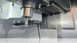
Acceleration is one of the most critical parameters in industrial motion systems. In CNC machines, servo drives, and robotics, acceleration does not only describe how fast velocity changes, it directly determines torque demand, vibration levels, structural stress, following error, and final surface quality.
This engineering guide explains acceleration from fundamental physics to advanced CNC S‑curve trajectory planning, including all governing equations used in real industrial control systems.
What Is Acceleration?
Acceleration is the rate of change of velocity with respect to time.
Because velocity has both magnitude and direction, acceleration is a vector quantity. It can:
- Increase speed
- Decrease speed
- Change direction
- Or combine all three
Mathematically:
a(t) = dv/dt
Since velocity is the derivative of position:
a(t) = d²x/dt²
SI unit of acceleration:
m/s²
Core Definitions Used in Motion Control
1) Average vs Instantaneous Acceleration
Average acceleration:
a_avg = Δv / Δt
Instantaneous acceleration:
a(t) = dv/dt = d²x/dt²
These definitions are fundamental in trajectory generators inside CNC and servo controllers.
2) Graphical Interpretation (Critical for CNC Tuning)
Slope of velocity–time graph = acceleration
Slope of position–time graph = velocity
Area under acceleration–time graph:
∫ a(t) dt = Δv
Area under velocity–time graph:
∫ v(t) dt = Δx
Understanding these relationships is essential when analyzing motion logs and drive trace data.
Equations of Motion in One Dimension
Constant Acceleration Case (Industrial Base Model)
If acceleration is constant:
v(t) = v0 + a·t
x(t) = x0 + v0·t + (1/2)·a·t²
Time-independent form:
v² = v0² + 2a(x − x0)
Engineering interpretation:
Constant acceleration implies constant net force (for constant mass), assuming friction and load remain approximately steady.
Acceleration in Curved and Multi-Axis Motion
In curved motion, acceleration splits into two components:
1) Tangential Acceleration (Speed Change)
at = dv/dt
2) Normal (Centripetal) Acceleration (Direction Change)
an = v²/ρ
Where ρ is the radius of curvature.
For circular motion (R = ρ):
an = v²/R = ω²R
These equations directly define cornering limits in CNC systems.
Acceleration Profiles in Servo and CNC Systems
In industrial motion control, an acceleration profile defines a(t), which generates velocity and position references.
Primary objectives:
- Reduce mechanical shock
- Minimize vibration and resonance
- Limit motor current peaks
- Improve surface finish
- Maintain stable following error
Profile 1: Rectangular (Step Acceleration)
Acceleration changes instantly:
a(t) → amax (step) → 0
Result:
Infinite jerk in ideal model → strong mechanical excitation.
Ramp time from v0 to v1:
T = (v1 − v0) / a
Displacement during ramp:
Δx = T · (v0 + v1) / 2
Used only in simple systems due to vibration risk.
Profile 2: Trapezoidal Velocity Profile
Most common industrial non‑jerk‑limited profile.
Phases:
- Constant acceleration to reach vmax
- Constant velocity section
- Constant deceleration
Distance required for acceleration and deceleration:
S_acc+dec = vmax² / amax
If S > S_acc+dec:
T_const = (S − S_acc+dec) / vmax
Total motion time:
T_total = T_const + 2(vmax / amax)
If S ≤ S_acc+dec → triangular profile.
Peak velocity:
v_peak = √(amax · S)
Total time (triangular case):
T_total = 2 · √(S / amax)
Widely used but excites structural modes at transition points.
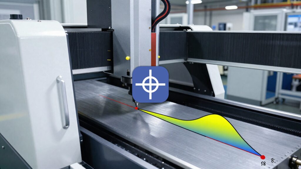
Profile 3: S-Curve (Jerk-Limited Motion)
Industrial standard in high‑performance CNC.
Jerk definition:
j(t) = da/dt
In trapezoidal motion, jerk is theoretically infinite at switching points.
In S‑curve motion:
Jerk is limited to jmax.
Typical relationship:
amax = jmax · Tj
Acceleration increases smoothly, holds, then decreases symmetrically.
Result:
- Reduced structural excitation
- Lower vibration
- Better contour accuracy
- Improved surface quality
Why Acceleration Directly Impacts CNC Performance
Trajectory generators produce reference motion followed by Position, Velocity, and Current loops.
Rotational axis torque requirement:
T_req = J_eq · α + T_load + T_fric
Linear axis force requirement:
F_req = m_eq · a + F_load + F_fric
If acceleration or jerk is too aggressive:
- Current spikes
- Mechanical resonance
- Increased following error
- Corner rounding
- Surface marks
Acceleration is therefore a design parameter — not just a kinematic variable.
Three Governing Motion Quantities
v(t) = dx/dt
a(t) = dv/dt
j(t) = da/dt
Without jerk limitation:
Step acceleration → infinite jerk → strong vibration.
Industrial solution:
Jerk-limited S-curve trajectory planning.
7-Segment S-Curve (Standard CNC Form)
Typical rest‑to‑rest motion contains 7 segments:
- +j (ramp acceleration up)
- Constant acceleration amax
- −j (reduce acceleration to zero)
- Constant velocity
- −j (increase deceleration)
- Constant deceleration
- +j (smooth stop)
Design parameters:
vmax – maximum velocity
amax – maximum acceleration
jmax – maximum jerk
Depending on travel distance S, segments (2), (4), or (6) may collapse.
Selecting amax and jmax (Engineering Guidelines)
1) Torque / Current Constraints
For rotational axes:
T_req = J_eq · α + T_load + T_fric
Choose amax such that T_req stays within drive limits.
For linear axes:
F_req = m_eq · a + F_load + F_fric
2) Structural Rigidity and Resonance
Flexible systems (gantry, long beams) are more sensitive to jerk than acceleration magnitude.
Practical rule:
- Ripple or vibration → reduce jmax
- Rigid but slow system → carefully increase amax
3) Look-Ahead and Corner Speed Limiting
For curved motion:
an = v² / R
Thus corner speed must satisfy:
v ≤ √(amax · R)
Even if straight-line speed is high, curvature imposes limits.
Practical CNC Engineering Notes
- High acceleration without jerk limitation reduces surface quality.
- S‑curve often improves finish more than lowering acceleration alone.
- If following error spikes at motion start:
- Reduce amax
- Tune velocity and position loops
- Apply resonance filters if necessary
- In short moves, axis rarely reaches vmax; amax and jmax dominate behavior.
Engineering Conclusion
Acceleration in motion control is not merely dv/dt. It defines torque demand, structural stress, dynamic stability, and machining accuracy.
High‑performance CNC systems require carefully selected amax and jmax values combined with jerk‑limited S‑curve trajectory planning to achieve precision, stability, and surface quality.
For professional CNC motion tuning and trajectory optimization, contact Radonix or use the chatbot in the bottom right corner.