Principles of Electrical Control Panel Layout for Components
Written by: Nima Rad, Content Specialist – Radonix
Standard Framework and Design Objectives
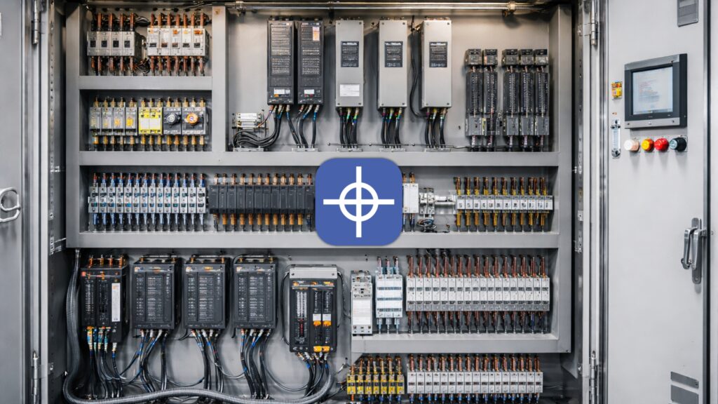
In industrial electrical control panels—whether for CNC machines, automation lines, pump stations, or packaging systems—component layout is never a matter of aesthetics or personal preference.
Layout decisions have a direct and measurable impact on electrical safety, operational stability, electromagnetic compatibility (EMC), thermal performance, serviceability, and fault‑finding speed.
Panels assembled without a clear layout logic often develop predictable problems over time: unexplained trips, PLC resets, intermittent servo or inverter faults, excessive internal heat, disorganized wiring, and extended downtime during maintenance.
These issues are rarely caused by component quality alone; they are almost always rooted in poor spatial planning and routing decisions.
The objective of a professional layout is therefore clear:
- The energy path—from power entry to protection, distribution, and final loads—must be short, visible, and logical.
- Control and signal circuits must be physically separated from high‑power and noise‑generating components.
- Heat generation and airflow must be planned from the start so all devices operate within their rated temperature limits.
- Earthing and bonding must be architected intentionally to ensure both safety and EMC performance.
- Every component must remain accessible for inspection, testing, replacement, and future expansion.
A layout that satisfies these goals is defensible, scalable, and reliable in real industrial environments.
Golden Rules of Control Panel Layout
Functional Zoning as the Foundation
Instead of arranging components by size or installation order, the enclosure should be divided into clear functional zones. This zoning approach is one of the most effective ways to reduce noise issues, simplify wiring, and improve long‑term serviceability.
Typical functional zones include:
- Incoming Power and Primary Protection
Main disconnect or isolator, circuit breakers or fuses, surge protection devices where required, and main busbars. - Power and Drive Section
Power contactors, soft starters, variable frequency drives (VFDs), servo drives, thermal overloads, braking resistors, reactors, and output filters. - DC Power and Distribution
Power supplies for 24 VDC or 12 VDC systems, DC‑UPS units if used, and fused DC distribution terminals. - Control and Logic
PLCs, I/O modules, interface relays, signal conditioners, and measurement modules. - Safety Systems
Safety relays or safety PLCs, safety contactors, emergency stop circuits, and interlocks. This zone should remain clearly identifiable and traceable. - Communication and Networking
Industrial Ethernet switches, routers, modems, and fieldbus modules.
Each zone should have its own dedicated wiring ducts and cable paths. Mixing power, control, and communication routes is a common source of EMC problems and maintenance errors.
Physical Separation of Power and Control
Power and signal separation must be enforced both in component placement and cable routing. Three‑phase motor cables, drive outputs, and high‑current conductors should never share ducts with control, encoder, analog, or network cables.
When cable crossings are unavoidable, they should occur at a 90‑degree angle. Long parallel runs between power and signal cables should be avoided entirely. Noise‑generating devices such as VFDs, servo drives, contactors, and coils must be positioned as far as practical from PLCs and low‑level signal circuits.
Thermal Management and Airflow Design
Thermal behavior is a design parameter, not an afterthought. Drives, large power supplies, transformers, and braking resistors generate significant heat and must be arranged to support natural convection.
Key principles include:
- Cool air should enter from the bottom of the enclosure and exit at the top.
- Ventilation paths must remain unobstructed.
- Forced ventilation should guide airflow through power zones without creating short‑circuit paths directly over sensitive control electronics.
- Adequate spacing must be maintained between heat‑generating devices to prevent localized hot spots.
Over‑compressed layouts raise internal temperatures and also make wiring brittle, difficult to modify, and prone to damage during maintenance.
Serviceability and Accessibility
Every component must be reachable for testing and replacement without dismantling large sections of the panel. Wiring should be performed from the front wherever possible, and flexible conductors must be used for devices mounted on the door.
Field terminals are typically placed at the bottom or along one side of the enclosure to simplify external cable entry. This improves installation efficiency and significantly reduces service time during commissioning or troubleshooting.
Earthing and Bonding as a System Architecture
Earthing and bonding must be designed into the panel from the beginning, not added at the final assembly stage. The backplate and enclosure body should be properly bonded, with paint or insulation removed at contact points to ensure metal‑to‑metal continuity.
Different earthing functions must be clearly defined:
- Protective Earth (PE) for personnel safety
- Functional or EMC Earthing for noise reduction and signal stability
Shielded cables—such as those used for encoders, analog signals, and industrial networks—must be terminated according to EMC best practices at the correct locations.

Practical Layout Pattern on the Mounting Plate
A commonly used and proven layout strategy follows a vertical functional flow:
- Top Section
Main power entry, disconnect, primary protection, and distribution busbars. - Middle Section (Power Zone)
Contactors, soft starters, VFDs, and servo drives, positioned with adequate spacing from control electronics and with short motor output paths. - Lower‑Middle Section (Control Zone)
DC power supplies, fused DC distribution, PLCs, I/O modules, and interface relays. - Bottom Section
Terminal blocks for sensors, actuators, motors, spindles, and pumps. Power terminals should be separated from signal terminals. PE terminals should be placed close to shielded cable entry points. - Door‑Mounted Devices
HMIs, pushbuttons, indicator lights, and emergency stop devices, wired with flexible conductors and protected against mechanical stress.
This mental model helps designers maintain consistency across projects and simplifies both documentation and field service.
Small Details with Major Impact
Wiring Duct Sizing and Cable Order
Ducts must be sized so they are not overfilled after final wiring. Extra capacity should be reserved for future modifications and for airflow within the duct. Cable routes should be defined during the layout phase, not improvised during assembly.
Circuit Separation for Safety and Diagnostics
Control circuits at 24 VDC, control circuits at 230 VAC, and three‑phase power circuits should be clearly separated physically and logically. Safety circuits should be short, clearly labeled, and easy to trace during inspections.
Suppression of Inductive Loads
Contactors, relays, and solenoid valves generate switching noise. Appropriate suppression components—diodes, RC snubbers, or varistors depending on supply type—should be used to reduce interference and extend component life.
Documentation as Part of the Layout Process
A high‑quality control panel is always accompanied by accurate documentation:
- Single‑line power diagrams
- Control schematics
- Terminal layouts and cable schedules
- Clear labeling of wires, terminals, and devices
Documentation created alongside the physical layout ensures consistency and reduces errors during commissioning and future upgrades.
Common Layout Mistakes and Their Direct Consequences
Placing PLCs or network equipment next to VFDs often results in random faults, analog signal noise, or PLC resets. Routing encoder cables parallel to motor cables can cause false pulses and servo errors. Ignoring thermal paths leads to drive trips and premature power supply failures.
Poor earthing, especially bonding over painted surfaces—creates unpredictable behavior and safety risks. Disorganized terminal layouts dramatically increase installation and maintenance time.
A disciplined layout approach prevents these failures before they occur and turns the control panel into a stable, serviceable, and scalable system rather than a source of recurring problems.
Contact Radonix or use the chatbot in the bottom right corner to learn how linear encoders integrate with Radonix control systems.